A digital clock is a commonly used electronic gadget. A digital clock keeps track of time and displays the current time through an output device. The users can set or reset the clock using buttons. Electronic clocks are built using microcontrollers and may or may not use a real-time clock.
Here, a digital clock is designed using Arduino, 7-segments, and MAX7219 IC. As microcontrollers are usually capable of generating delays of a precise interval, this basic digital clock is built using microcontroller features alone. The digital clock designed here displays the current time and allows users to set or reset time.
Components Required
- Arduino UNO x1
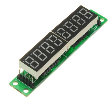
- 7-Segments x6
- MAX7219 IC x1
- Push buttons x3
- Breadboard x1
- Jumper wires or connecting wires
Prerequisites
Circuit Connections
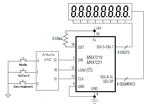
The digital clock designed here is based on the MAX7219 IC-based 7-segment driver module. MAX7219 is an 8-digit common-cathode LED display driver. It allows interfacing a microcontroller to 7-segment display units up to 8 digits. In the module, the data pins of the 7-segments are connected to SEG A to SEG G and DP pins of MAX7219. The common-cathode terminals of the segments are connected to the DIG0 to DIG7 pins of MAX7219. Pins 4 and 9 of the IC are hard-wired to ground, and pin 19 is connected to the 5V terminal. The pin 18 of MAX7219 is also connected to 5V DC via a suitable resistor. The DIN, LOAD, and CLK pins of the IC can be connected to digital I/O pins of Arduino.
MAX7219 communicates with Arduino using an SPI-compatible interface. The DIN, LOAD, and CLK pins of the IC are connected to the pins 12, 10, and 11 of the Arduino UNO, respectively. The MAX7219 module is supplied 5V DC and ground from the Arduino itself.
Along with the MAX7219 IC-based 7-segment driver, 3 push buttons are also connected to the Arduino. These pushbuttons are interfaced at pins 0, 1, and 2 of Arduino UNO. These Arduino pins are internally pulled up. The button at pin 0 controls the mode of the clock. The button at pin 1 allows selecting seconds, minutes, and hours. The button at pin 2 increments the selected clock element, seconds, minutes, or hours.
 Arduino Sketch
How the circuit works
There are 6 7-segments used with MAX7219 IC. A pair of 7-segments is used each to display seconds, minutes, and hours. The clock operates in two modes – normal mode (mode 0) and time setting mode (mode 1). In normal mode, the clock simply displays the current time, and Arduino updates it every second.
In time setting mode, the user can set the time using push buttons. The pushbutton at pin 0 of Arduino switches the clock between the two modes. The push buttons at pins 1 and 2 are operational only when the clock is in time-setting mode. The pushbutton at pin 1 allows switching to the selection of seconds, minutes, and hours. The push button at pin 2 increments the selected time element – seconds, minutes, or hours. If the seconds or minutes is incremented above 59 or hours is incremented above 12, they are reset to 0.
How the code works
The Arduino sketch begins by importing the SPI library of Arduino. The global variables are defined to assign pin numbers connected to DIN, CLK, and LOAD pins of MAX7219 IC. A variable of an array type is defined to store 16-bit commands for MAX7219. The variables are defined to store values of seconds, minutes, hours, clock mode, and select.
A character table is stored in the flash memory of Arduino UNO using PROGMEM construct. This table contains the bytes that must be written to the LED segments for displaying digits 0 to 9.
A function spiTransfer() is defined that shiftOut() function to transfer 16-bit data to MAX7219 IC. Each 16-bit data contains two bytes, the first byte is the address of the MAX7219 register, and the second byte is the data to be written to a selected register. Both bytes are passed as arguments to this user-defined function.
A function clearDisplay() is defined, in which, spiTransfer() function is used to write 0x00 to all the digit registers clearing all the digits. A function shutdown() is defined, which uses spiTransfer() function to write data to the shutdown mode register of MAX7219.
A function init_7seg() is defined to initialize the display. In the function, first, the MOSI, SCLK, and CS pins are set to digital output. The CS pin is set to HIGH to select MAX7219 on the SPI bus. A value of 0x00 is transferred to display test register (register address 15 or 0x0F) using spiTransfer() function to set MAX7219 to normal mode. A value of 0x07 is transferred to the scan limit register (register address 11 or 0x0B), allowing all 8 digits. A value of 0x00 is transferred to the decode mode register (register address 9 or 0x09) to select no decode for all digits.
A function setChar() is defined that writes a value to a digit register of MAX7219. Both value and digit are set as parameters of the function. In this function, first, data validation for digit number and the value passed is done. The verified value is passed to a given digit register using spiTransfer() function.
In the setup() function, init_7seg() and shutdown(false) functions are called. The spiTransfer(10, 8) function is called to set the intensity of the display. The display is cleared by calling the clearDisplay() function. The Arduino pins interfaced to push buttons are set as digital input using the pinMode() function.
In the loop() function, Arduino first checks for the pushbutton’s status at pin 0. If the button is pressed, it toggles the clock mode. The default mode is 0 or normal. By default, when the clock is powered on, it goes in normal mode and starts clocking from 12:00:00.
If the clock mode is 0, i.e., normal, Arduino updates the 7-segments with the current values of seconds, minutes, and hours every second using the setChar() function. If the clockmode is 1, i.e., time setting mode, Arduino checks the status of buttons at pins 1 and 2. If the button at pin 1 is pressed, it changes the select variable’s value, and accordingly, seconds, minutes, or hours are selected. If the button at pin 2 is pressed, the selected time element – seconds, minutes, or hours is increased by 1. When the user again presses the button at pin 0, the clock switches back to normal mode, clocking from the user’s time set.
Result
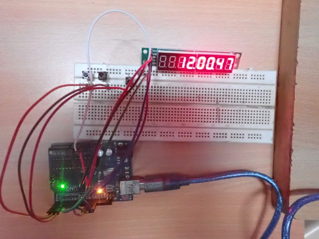
OLYMPUS DIGITAL CAMERA
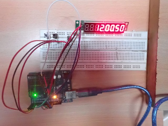
OLYMPUS DIGITAL CAMERA
Demonstration video
Filed Under: Arduino Projects, Microcontroller Projects
Log in to leave a comment:
Lost your password?
Don't have an account? Register here