This article is an improved variant of Digital clock using RTC DS12C887 and 8051 with time set. In the earlier article, we discussed the basics of extracting data from the RTC DS12C887 using the 8051 microcontroller (AT89C51). This article is in continuation to the above article and introduces you to the concept of handling interrupts for extracting time and other information from the RTC.
Interrupts offer a great flexibility to handle RTC. Interrupts have several advantages over the method of polling as discussed in the previous article. It reduces the unnecessary usage of microcontroller’s memory and processing powers, thereby keeping the processor free for other use. RTC 12C887 has three interrupts, namely, Alarm interrupt, Periodic interrupt & Update ended interrupt. For detailed information, check RTC interrupts. The free source code for the program is available in C.
This article assumes that the user is aware of real time clock and the basic interfacing of DS12C887 with 8051 microcontroller (AT89C51) including the pin description, memory and registers of RTC DS 12C887.
RTC 12C887 has three interrupts, namely, Alarm interrupt, Periodic interrupt & Update ended interrupt. For detailed information, check RTC interrupts. All the three interrupts works independent of each other.
Whenever an interrupt of DS12C887 occurs the following events take place:
1. The bit 7 and the corresponding interrupt flag of the Register C is set to 1.
2. The IRQ pin goes low only if the enable bit of the corresponding interrupt is set in Register B.
Steps to handle interrupt:
1. Connect the IRQ pin of the RTC to external hardware interrupt input pin of the microcontroller.
2. Initialize the external hardware interrupts in the microcontroller to receive interrupt from the RTC.
3. Initialize the interrupt(s) of the RTC to be used by configuring the corresponding bits of the Register B.
4. Whenever an interrupt occurs read the value of Register C to check which interrupt has occurred.
Register B and C are used to handle interrupts. Register B is used to enable the interrupts. By setting the bits 4-6 in this register the corresponding interrupt is enabled.
Register C is a read only register which tells as to which interrupt has occurred by setting the corresponding flag to high whenever an interrupt has occurred. Check DS12C887 for more details on Register C. Whenever an interrupt occurs, the bit 7 of this register gets set along with the corresponding flag bit of the interrupt which has occurred. The values of flag bits get cleared either by giving a low to the RESET pin or simply reading the value of Register C.
The Register C is updated every time an interrupt occurs irrespective of whether we are using the interrupt or not. In case this Register C is not cleared after the first interrupt and the second interrupt has occurred than in that case the value of the flag corresponding to the first interrupt is retained in the Register C.
The pin 19 (interrupt request output, IRQ pin) of the RTC is used to indicate the occurrence of an interrupt. This is an output pin of the RTC and it goes low only when the following conditions are matched simultaneously:
1. Any of the three interrupt occurs.
2. The enable bit of the corresponding interrupt is set in Register B.
This pin can be used to provide external hardware interrupt to the microcontroller. This pin is multiplexed to all the three interrupts i.e., it goes low whenever any of the interrupt occurs and hence indicates that an interrupt has occurred. However to identify which interrupt has occurred it is required to read the value of the Register C. The IRQ pin will remain low, until the flag bit of the interrupt remains high in the Register C and the corresponding enable pin in Register B is set. Once an interrupt has occurred it is required to clear the IRQ pin so that the RTC is ready to serve the next interrupt. The IRQ pin can be cleared by either of the two ways:
1. A low signal on reset pin will clear the IRQ pin.
2. By reading the Register C, the IRQ pin will be cleared by the processor.
In this code we have used the second method to clear the IRQ pin. Reading the register C will also tell as to which interrupt has occurred.
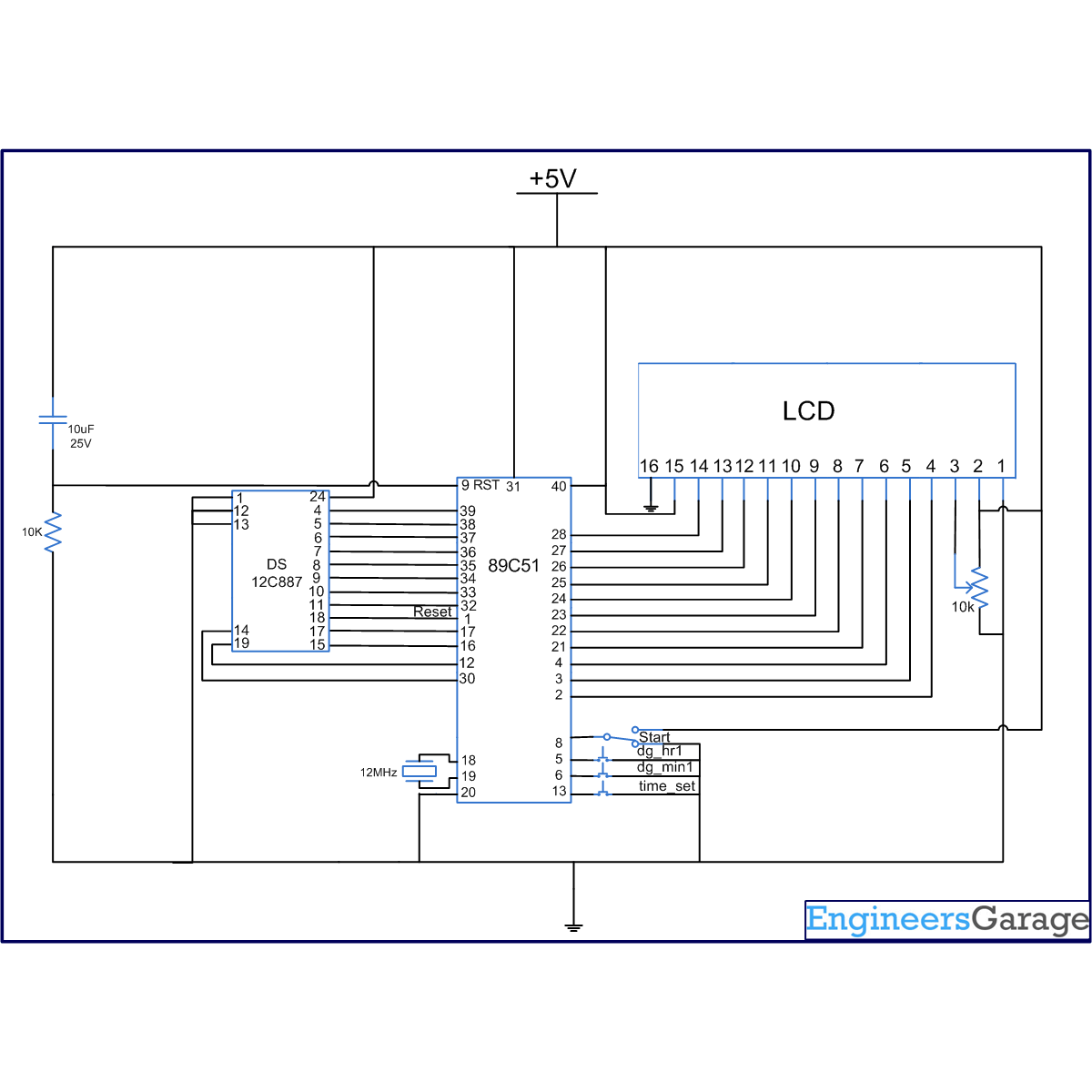
The connection of the RTC DS12C887 with the microcontroller is shown in the circuit diagram. This article uses update interrupt to keep the track of the time. Every time the update interrupt comes, the clock is incremented by one second. The output is displayed on the LCD. The clock presented in this article also has the provision of setting the time. The clock uses external interrupt 2 of the microcontroller AT89C51 for setting the time. A user can set time by pressing the switch connected to pin 13 of the microcontroller, which is interrupt 2. The hour and minutes can be set using pin 5 and pin 6 of the controller AT89C51 respectively. Once the time is set, the user needs to press the start pin (pin 8 of controller) to start the clock. The code for interfacing RTC DS12C887 is written in C.
Project Source Code
###
//Program for an LCD based clock using RTC DS12C887 and 8051 microcontroller (AT89C51) using update interrupt /*24 hr clock set p3^3=0,then start=0 them set time by dig_hr1 & dig_min1, then remove p3^3 & start */ #include<reg51.h> #include<absacc.h> #define dataport P2 #define port P1 sbit reset = port^0; sbit rs = port^1; sbit rw = port^2; sbit e = port^3; sbit dig_hr1=port^4; sbit dig_min1=port^5; sbit start=port^6; int hr0 ,hr1=0; int min0,min1=0; int sec0,sec1=0; unsigned char temp,hr,min,sec,num[60]={0X00,0X01,0X02,0X03,0X04,0X05,0X06,0X07,0X08,0X09,0X10,0X11,0X12,0X13,0X14,0X15,0X16,0X17,0X18,0X19,0X20,0X21,0X22,0X23,0X24,0X25,0X26,0X27,0X28,0X29,0X30,0X31,0X32,0X33,0X34,0X35,0X36,0X37,0X38,0X39,0X40,0X41,0X42,0X43,0X44,0X45,0X46,0X47,0X48,0X49,0X50,0X51,0X52,0X53,0X54,0X55,0X56,0X57,0X58,0X59}; void delay(unsigned int msec ) { int i ,j ; for(i=0;i<msec;i++) for(j=0; j<1275; j++); } void lcd_cmd(unsigned char item) { dataport = item; rs= 0; rw=0; e=1; delay(1); e=0; return; } // DATA SENDING FUNCTION void lcd_data(unsigned char item) { dataport = item; rs= 1; rw=0; e=1; delay(1); e=0; return; } void lcd_data_string(unsigned char *str) { int i=0; while(str[i]!='�') { lcd_data(str[i]); i++; delay(1); } return; } lcd_data_int(int time_val) { int int_amt; int_amt=time_val/10; lcd_data(int_amt+48); int_amt=time_val%10; lcd_data(int_amt+48); } void lcd() // Function to initialize LCD { lcd_cmd(0x38); delay(5); lcd_cmd(0x0F); delay(5); lcd_cmd(0x80); delay(5); } void set_rtc_time() // Function to set time in RTC { XBYTE[10]=0x20; XBYTE[11]=0x82; XBYTE[0]=0x00; XBYTE[2]=min; XBYTE[4]=hr; XBYTE[7]=0x01; XBYTE[8]=0x01; XBYTE[9]=0x10; XBYTE[1]=0xFF; XBYTE[3]=0xFF; XBYTE[5]=0xFF; XBYTE[11]=0x12; } void set_hr1() { hr1++; if(hr1>23) hr1=0; lcd_cmd(0xc3); lcd_data_int(hr1); lcd_data(':'); hr0=hr1; } void set_min1() { min1++; if(min1>59) min1=0; lcd_cmd(0xc6); lcd_data_int(min1); min0=min1; } void set_time() interrupt 2 // Time set { lcd_cmd(0x01); if(start==0) { lcd_data_string("SET TIMING"); lcd_cmd(0xc3); lcd_data_int(hr1); lcd_data(':'); lcd_data_int(min1); while(start==0) { delay(10); if(dig_hr1==0) set_hr1(); if(dig_min1==0) set_min1(); } } lcd_cmd(0x01); hr=num[hr1]; min=num[min1]; set_rtc_time(); } bcdconv(unsigned char mybyte) { unsigned char x,y; x= mybyte & 0x0F; x=x | 0x30; y= mybyte & 0xF0; y=y>>4; y=y | 0x30; lcd_data(y); lcd_data(x); } void read_rtc_display() interrupt 0 // Alarm interrupt { lcd_cmd(0x01); lcd_cmd(0x80); lcd_data_string("TIME:"); lcd_cmd(0X87); reset=0; reset=1; XBYTE[11]=0x12; hr=XBYTE[4]; temp=0x87; bcdconv(hr); lcd_data(':'); min=XBYTE[2]; bcdconv(min); lcd_data(':'); sec=XBYTE[0]; bcdconv(sec); } void main() { reset=1; lcd(); XBYTE[10]=0x20; XBYTE[11]=0x12; lcd_cmd(0x01); IE=0x85; while(1); }###
Circuit Diagrams
Project Components
Project Video
Filed Under: 8051 Microcontroller.
Filed Under: 8051 Microcontroller.

Questions related to this article?
👉Ask and discuss on Electro-Tech-Online.com and EDAboard.com forums.
Tell Us What You Think!!
You must be logged in to post a comment.