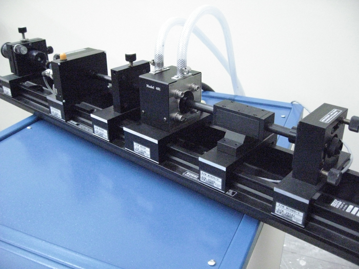
Fig. 1: Image of Diode Pump
Diode Pump is a rectifier circuit that makes a varying AC signal output to a DC voltage relative to the peak-to-peak voltage across the AC waveform. Diode pump can be used to switch on a driver transistor or to give in digital or analog circuits for DC measurements. The design note given here explains the working of the diode pump.
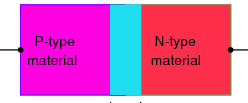
Fig. 2: Image showing Working of the Diode Pump
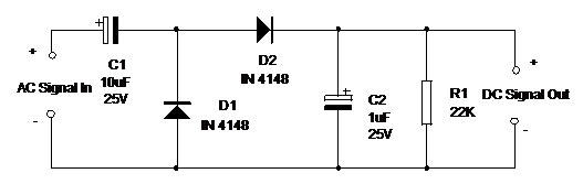
The Diode Pump Circuit essentially consists of two rectifier diodes, one buffer capacitor and one resistor. The circuit of a typical diode pump is shown in circuit diagram tab.
Working of each component is as follows:
1. C1 – This capacitor receives the Ac signals from the Audio and transfers the full AC wave form across it. But the midway level is still the same, therefore only the voltage above 0 volt passes through the diode D2.
2. D1 and D2 – When the waveform from C1 tries to go below 0 volt, D1 takes current from the negative rail. Therefore voltage never goes below 0 volt at the junction of C1 and D1. When the waveform from C1 rises, the rise is from minimum (0 volts) as imposed by D1. Since the waveform is not changing, the total voltage between the upper and lower peak of wave is then pumped into diode D2 and then into C2. But the actual DC voltage from D2 will be slightly lesser than the full peak-to-peak voltage due to the forward voltage drop of D1 and D2.
3. C2– This capacitor stores the current pumped through D2. It acts as a buffer and prevents the fluctuation of DC as the AC waveform swings. Value of C2 depends on the input current as well as the current to be stored. That is, 1uF is an optimum value but it can be increased to 10 uF depending on the application.
4. R1 – when the input signal ceases, the stored current from C2 will discharge through R1.Value of R1 is selected to suit the value of C2. A higher value resistor will discharge the capacitor slowly when the input signal ceases.
By including the Diode Pump between the circuit giving AC output and a Driver circuit, the DC voltage generated can be maintained at the level of the AC signal. That is no voltage drop develops.
Fig. 3: Image Of Diode Pump
Diode pump circuits are found in lasers and are used in solid-state lasers which are a fairly popular laser type in several experiments as well as commercial products.
Circuit Diagrams
Filed Under: Electronic Projects

Questions related to this article?
👉Ask and discuss on Electro-Tech-Online.com and EDAboard.com forums.
Tell Us What You Think!!
You must be logged in to post a comment.