
Fig. 1: Symbol of a Diode

Fig. 2: Graph showing electrical characterstics of an Ideal Diode
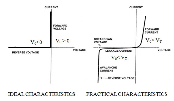
Fig. 3: Graph showing comparison of electrical characterstics of Ideal and Practical Diodes
Types of Diodes
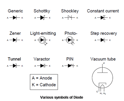
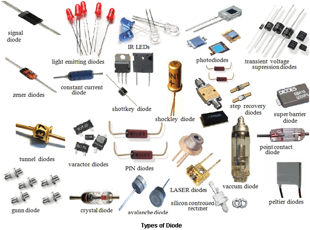
Fig. 5: Image showing various types of diodes

Fig. 6: Image showing construction of a generic diode
Construction

Fig. 7: Graph of Linear Graded Dioe and Step Graded Diode
Principle and Operation
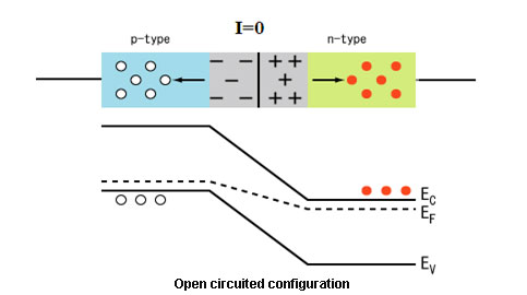
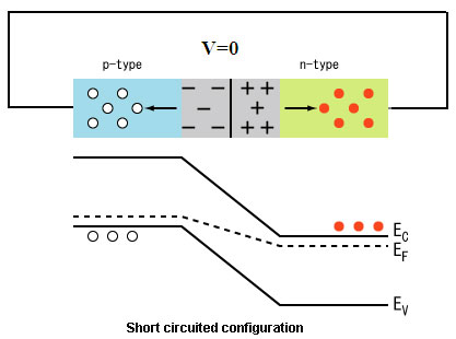
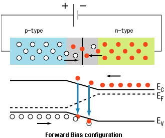
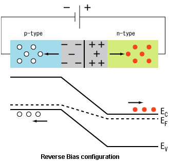
Fig. 11: Image showing working of diode in reverse bias configuration
Characteristics

Fig. 12: Graph showing characterstics curve of diode
The current that flows through a diode is given by the equation:

where ID – diode current. (Positive for forward and negative for reverse)
 – factor dependent upon the nature of semiconductor. (1 for
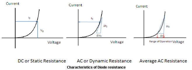
Fig. 13: Graph showing characterstics of diode resistance
 where CT – transition capacitance
 where CD – diffusion capacitance
 – time interval for change in voltage
 The diffusion capacitance at high frequencies is inversely proportional to the frequency and is given by the formula:
  Note: The variation of diffusion capacitance with applied voltage is used in the design of varactor.
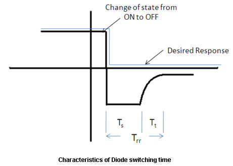
Fig. 14: Graph showing characterstics of diode switching time
Identification:
A diode is marked with a bar which indicates the cathode terminal of a diode which is as shown in the figure below:
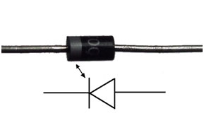
Fig . 15: Image showing identification of diode terminals
Applications
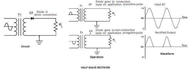
Fig. 16: Circuit Diagram of Diode based Half Wave Rectifier
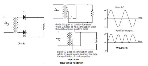
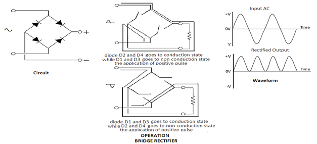
Fig. 18: Circuit Diagram of Diode based Bridge Rectifier

Fig. 19: Circuit Diagram of Diode based Clipper
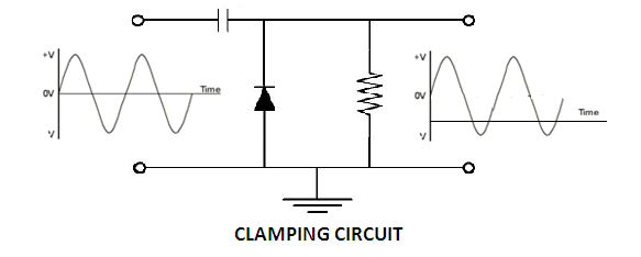
Fig. 20: Circuit Diagram of Diode based Clamper
Datasheet Analysis
Rectifying Diodes in Market:
· Another series of diodes is IN5400 to IN5408 with maximum forward voltage of 1.2 V and 3A being the maximum rectifying current. The maximum reverse current are 5 uA and PIV (Peak Inverse voltage) varies from 50V to 1000V.
Testing of a Diode
Filed Under: Tech Articles


Questions related to this article?
👉Ask and discuss on EDAboard.com and Electro-Tech-Online.com forums.
Tell Us What You Think!!
You must be logged in to post a comment.