Engineers Garage

  • Electronic Projects & Tutorials
    • Electronic Projects
      • Arduino Projects
      • AVR
      • Raspberry pi
      • ESP8266
      • BeagleBone
      • 8051 Microcontroller
      • ARM
      • PIC Microcontroller
      • STM32
    • Tutorials
      • Audio Electronics
      • Battery Management
      • Brainwave
      • Electric Vehicles
      • EMI/EMC/RFI
      • Hardware Filters
      • IoT tutorials
      • Power Tutorials
      • Python
      • Sensors
      • USB
      • VHDL
    • Circuit Design
    • Project Videos
    • Components
  • Articles
    • Tech Articles
    • Insight
    • Invention Stories
    • How to
    • What Is
  • News
    • Electronic Product News
    • Business News
    • Company/Start-up News
    • DIY Reviews
    • Guest Post
  • Forums
    • EDABoard.com
    • Electro-Tech-Online
    • EG Forum Archive
  • DigiKey Store
    • Cables, Wires
    • Connectors, Interconnect
    • Discrete
    • Electromechanical
    • Embedded Computers
    • Enclosures, Hardware, Office
    • Integrated Circuits (ICs)
    • Isolators
    • LED/Optoelectronics
    • Passive
    • Power, Circuit Protection
    • Programmers
    • RF, Wireless
    • Semiconductors
    • Sensors, Transducers
    • Test Products
    • Tools
  • Learn
    • eBooks/Tech Tips
    • Design Guides
    • Learning Center
    • Tech Toolboxes
    • Webinars & Digital Events
  • Resources
    • Digital Issues
    • EE Training Days
    • LEAP Awards
    • Podcasts
    • Webinars / Digital Events
    • White Papers
    • Engineering Diversity & Inclusion
    • DesignFast
  • Guest Post Guidelines
  • Advertise
  • Subscribe

Direction Pointer

By Ashutosh Bhatt November 26, 2013

Many times we find an arrow pointing direction of a shop, in movie halls giving you the indication of exit door or in malls to give you direction of staircase or wash room. But in night or in dim light it becomes quite difficult to find the way. So at such places you can install this direction pointer which will produce an eye catching appearance than any other ordinary direction pointer.

[[wysiwyg_imageupload:11098:]]

Fig. 1: Prototype of Direction Pointer Circuit on Breadboard 


This simple direction pointer circuit is made with the help of an IC CD7404 with few more commonly used components. CD7404 is the most commonly used Complementary Metal Oxide Semiconductor (CMOS) chip. It comes in a 14 pin Dual Inline Package (DIP). It has small notch on one side which identifies as pin 1. It consists of 6 independent NOT gate on a single chip. Each gate has 1 inputs and 1 output. Working voltage range of IC is from 5V to 16V. It can deliver approx.10mA at 12V but this can be reduced as power supply voltage reduces.

IC consist of 14 pin and pin 7 and 14 is connected to battery or DC power supply. Negative is connected to pin 7 and pin 14 is connected to power supply. As we know it has six gates we call it NI1, NI2, NI3, NI4 and so on. In first gate NI1 pin 1 is for inputs and pin 2 is for output. As you can see in the circuit below, its outputs goes low when input is high and its output becomes high when input is low, that’s why it is known as inverter IC.
inverter ic
Fig. 2: Pin Diagram of  IC CD7404 
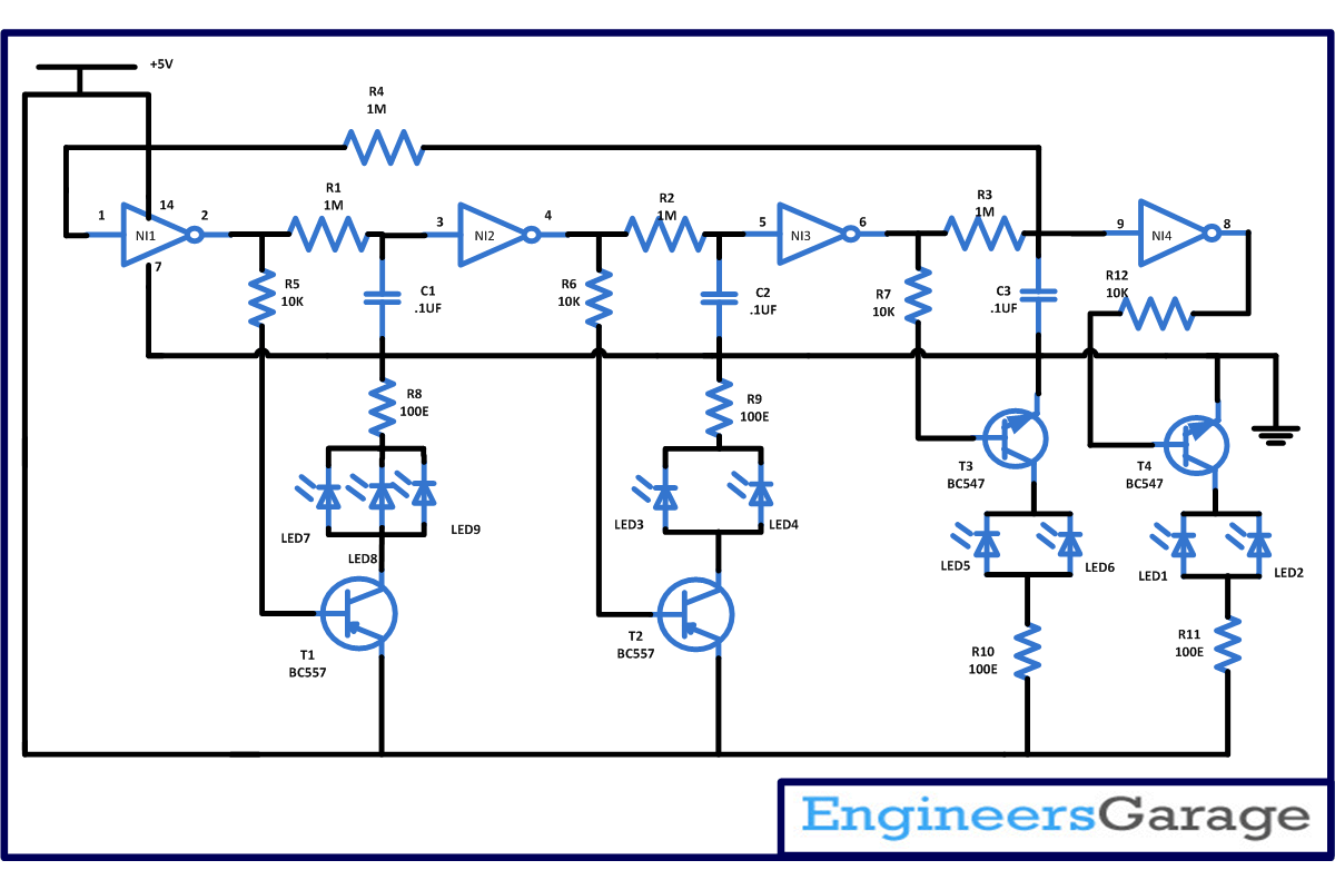
In this circuit four sets of LED are arranged in the form of arrow and each set is light up one by one to give you indication. When power supply is provided, input pin of gate NI4 and NI1 are at low level as initially capacitor will behave like a short capacitor and inputs of both the gates are connected through a resistor R4. Because of this output pin 8 of NI4 becomes high and it will drive the transistor T1 into conduction and LED 1 and LED 2 connected to it start glowing. 
At this time low at input pin 1 of NI1 make the output pin 2 high (therefore transistor T1 will not conduct) which is connected to input pin 3 of NI2 therefore after certain delay because of resistor R1 and capacitor C1 output pin 4 of NI3 becomes low and it will drive the transistor T2 and LED 3 and LED 4 connected to it start glowing. 
 
 Now again pin 4 is connected with pin 5 of NI3 so it will make the output pin 6 high and the transistor T3 connected to it start conducting and LED 5 and LED 6 will glow after some delay because of resistor R2 and capacitor C2. Now this high is again feed to pin 1 of NI1 and pin 9 of NI4( transistor T4 will not conduct) and at this time output pin 2 of NI1 become low and transistor T1 comes into conduction and LED 7, LED 8 and LED 9 will glow after some delay because of resistor R3 and capacitor C3. And this cycle is repeated until power supply is provided. 
 
Arrange the LED’s in the form of arrow to point the direction. In order to slow down the speed of glowing LED’s increase the value of resistor R1, R2 and R3 and capacitor C1, C2 and C3.

Circuit Diagrams

Direction-pointer-circuit-diagram

Project Components

  • Capacitor
  • IC 74LS04
  • LED
  • Resistor


Filed Under: Electronic Projects
Tagged With: direction pointer
 

Next Article

← Previous Article
Next Article →

Questions related to this article?
👉Ask and discuss on Electro-Tech-Online.com and EDAboard.com forums.


Tell Us What You Think!! Cancel reply

You must be logged in to post a comment.

EE TECH TOOLBOX

“ee
Tech Toolbox: 5G Technology
This Tech Toolbox covers the basics of 5G technology plus a story about how engineers designed and built a prototype DSL router mostly from old cellphone parts. Download this first 5G/wired/wireless communications Tech Toolbox to learn more!

EE Learning Center

EE Learning Center
“engineers
EXPAND YOUR KNOWLEDGE AND STAY CONNECTED
Get the latest info on technologies, tools and strategies for EE professionals.

HAVE A QUESTION?

Have a technical question about an article or other engineering questions? Check out our engineering forums EDABoard.com and Electro-Tech-Online.com where you can get those questions asked and answered by your peers!


RSS EDABOARD.com Discussions

  • Safe Current and Power Density Limits in PCB Copper(in A/m² and W/m³) simulation
  • The Analog Gods Hate Me
  • Help with hall effect sensors for a milwuakee impact driver
  • How to find the resonance frequency and impedance of a planar spiral coil in HFSS?
  • Diode recovery test Irrm timing.

RSS Electro-Tech-Online.com Discussions

  • Raise your hand if your car had one of these:
  • Simple LED Analog Clock Idea
  • Kawai KDP 80 Electronic Piano Dead
  • Tektronix 2235 channel 1 trace unstable
  • How to make string LEDs?

Featured – LoRa/LoRaWan Series

  • What is the LoRaWAN network and how does it work?
  • Understanding LoRa architecture: nodes, gateways, and servers
  • Revolutionizing RF: LoRa applications and advantages
  • How to build a LoRa gateway using Raspberry Pi
  • How LoRa enables long-range communication
  • How communication works between two LoRa end-node devices

Recent Articles

  • Tria modules integrate edge AI processing with multi-core processors
  • pSemi introduces RF switch with 52 dBm PMAX,PEAK and 90-dBm IIP3 linearity
  • XP Power launches 1.3 kW power supply with 58.9 W/cm³ density
  • How to enable Wi-Fi provisioning in ESP32-based IoT products
  • Amphenol RF introduces FAKRA to SMA adapters with 4 GHz operating frequency

EE ENGINEERING TRAINING DAYS

engineering

Submit a Guest Post

submit a guest post
Engineers Garage
  • Analog IC TIps
  • Connector Tips
  • Battery Power Tips
  • DesignFast
  • EDABoard Forums
  • EE World Online
  • Electro-Tech-Online Forums
  • EV Engineering
  • Microcontroller Tips
  • Power Electronic Tips
  • Sensor Tips
  • Test and Measurement Tips
  • 5G Technology World
  • Subscribe to our newsletter
  • About Us
  • Contact Us
  • Advertise

Copyright © 2025 WTWH Media LLC. All Rights Reserved. The material on this site may not be reproduced, distributed, transmitted, cached or otherwise used, except with the prior written permission of WTWH Media
Privacy Policy

Search Engineers Garage

  • Electronic Projects & Tutorials
    • Electronic Projects
      • Arduino Projects
      • AVR
      • Raspberry pi
      • ESP8266
      • BeagleBone
      • 8051 Microcontroller
      • ARM
      • PIC Microcontroller
      • STM32
    • Tutorials
      • Audio Electronics
      • Battery Management
      • Brainwave
      • Electric Vehicles
      • EMI/EMC/RFI
      • Hardware Filters
      • IoT tutorials
      • Power Tutorials
      • Python
      • Sensors
      • USB
      • VHDL
    • Circuit Design
    • Project Videos
    • Components
  • Articles
    • Tech Articles
    • Insight
    • Invention Stories
    • How to
    • What Is
  • News
    • Electronic Product News
    • Business News
    • Company/Start-up News
    • DIY Reviews
    • Guest Post
  • Forums
    • EDABoard.com
    • Electro-Tech-Online
    • EG Forum Archive
  • DigiKey Store
    • Cables, Wires
    • Connectors, Interconnect
    • Discrete
    • Electromechanical
    • Embedded Computers
    • Enclosures, Hardware, Office
    • Integrated Circuits (ICs)
    • Isolators
    • LED/Optoelectronics
    • Passive
    • Power, Circuit Protection
    • Programmers
    • RF, Wireless
    • Semiconductors
    • Sensors, Transducers
    • Test Products
    • Tools
  • Learn
    • eBooks/Tech Tips
    • Design Guides
    • Learning Center
    • Tech Toolboxes
    • Webinars & Digital Events
  • Resources
    • Digital Issues
    • EE Training Days
    • LEAP Awards
    • Podcasts
    • Webinars / Digital Events
    • White Papers
    • Engineering Diversity & Inclusion
    • DesignFast
  • Guest Post Guidelines
  • Advertise
  • Subscribe