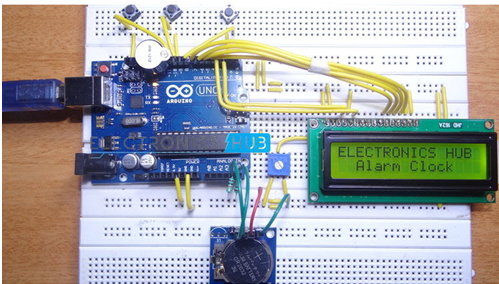
In another extraordinary project of electronics hub, they have designed an Arduino based Real Time Clock with alarm. The gripping part of this clock is that it is battery powered and it runs when the microcontroller is reprogrammed or there is no external power. As soon as the power is reinstated, RTC shows the real time regardless of the fact that the power was off for long duration.

Real Time Clocks are often useful in data logging applications, time stamps, alarms, timers, clock builds etc. This sort of functionality is often seen in computers, where this real time clocks are referred as CMOS (Complementary Metal Oxide Semiconductor).
Generally, microcontrollers and microprocessors have built in timers but are workable only when the power is turned on. Hence, when the microcontroller is coupled with the power supply, the internal timers automatically reset to 0. So, to avoid resetting in case of power cut, a separate RTC chip is encompassed in different applications like data loggers.
Taking cue from the benefits of a Real Time Clock that displays accurate time and date, this project is designed while featuring an alarm clock. RTC ICs DS1307 is used along with Arduino in this project and the battery is attached to the RTC in separate slot, which displays clock and calendar with all timekeeping functions.
The components used in this project are Arduino UNO, DS 1307 RTC Module, Push Buttons, 16X2 LCD Display, Buzzer, 10 KΩ and 10 KΩ POT. The communication between microcontroller and RTC IC DS1307 is serial I2C bidirectional bus.
The circuit is designed with two pins on Arduino for I2C communication, where analog pins 4 and 5 acts as SDA (Serial Data) and SCL (Serial Clock) and both the pins of RTC are dragged high using 10KΩ resistors. The six pins of LCD that is used to display the clock is connected to Arduino while three buttons are for setting the alarm along with buzzer, which is connected to pin 11 of Arduino.
The alarm is set by pressing the set button, which jumps to the alarm mode and demands for hours with current time being displayed. As the increment button is pressed to change the hours, the hours will be incremented between 0 and 23 in 24 hour format.
The next button is pressed to go to minute’s tab, where the same procedure is followed and the alarm is set. The values are stored in the EEPROM of the Arduino that continuously compares time with the current time. When the stored values and current value matches, it triggers the buzzer for the alarm.
After the alarm is stored in the internal EEPROM of Arduino, the time and alarm keeps running as there is a backup supply to the RTC. The connections established are shown in the circuit diagram and by modifying the code of Arduino, the functions like snooze and multiple alarms can be added. For codes, video and circuit diagram, visit the following website
Filed Under: Reviews


Questions related to this article?
👉Ask and discuss on EDAboard.com and Electro-Tech-Online.com forums.
Tell Us What You Think!!
You must be logged in to post a comment.