This is a project based on Arduino board which can measure the unknown DC current values. When wefed the current to a load device through the breadboard circuit, the 16*2 LCD displays that current value. The project uses an Arduino pro mini board whose ADC feature is used along with the concept of Ohm’s law to develop this ammeter.

Fig. 1: Prototype of Arduino based Ammeter
Architecture of the project
The entire project can be divided into three basic blocks;
1) DC CurrentSensor Unit
2) Processor Unit
3) Display Unit

Fig. 2: Overview of Arduino based Ammeter
The DC Current Sensor Unit allows the current to flow through adevice whose current consumption needs to be measured. The Sensor Unit produces two voltages both in the range of 0 to 5V, whose difference is proportional to the amount of current flowing through the Sensor unit.
The Processor Unit can take two input voltagesboth in the range of 0 to 5V. This unit takes the Sensor Unit’s output as input voltages and uses the ADC to read these voltages. An Algorithm is then applied to calculate the DC current flowing through the sensor. The unit then sends a 4bit data to the Display Unit to display the current consumption of the device.
The Display Unit takes the 4bit data from the Processor Unit and produces a 16*2 display for the current consumption of the device.
1) DC Current Sensor Unit
The Current Sensor in this project is a single low valued resistor through which the current flows to the load device.The basic principle of current measurement is based on the Ohm’s law. Ohm’s law states that the current flowing through a resistive path is directly proportional to the voltage difference across the resistive path and inversely proportional to the resistance of the path.
I = V / R
Where;
I is the current flowing through a resistive path
V is the difference in voltage across the path
R is the resistance of the path

Fig. 3: Circuit Diagram of Current Sensor
Consider the above circuit in which the current ‘I’ is flowing through a resistor ‘R’ producing Voltage ‘V1’ at one end and the voltage ‘V2’ at the other end. Hence the voltage difference across the resistor,
V = V2 – V1
In our project we implement such a resistor in the current flowing path whose resistance value is known. Then we measure the voltage at both the ends of the resistor to calculate the current flow with the help of the following equation.
I = (V2 – V1) / R

Fig. 4: Circuit Diagram of Current Meter
As shown in the above diagram the current that need to flow through a device is fed through the resistor ‘R’ of the current meter for calculating the value of the current flowing. As the current flows, V1 and V2 appears which will then be read using the ADC module of the Arduino microcontroller
Selecting the value of R:
The value of ‘R’ should be selected in such a way that it should not affect the performance of the Device which is consuming the current. Using a high value resistor will cause substantial voltage drop ‘V’ across it as the current flows, which leaves the Device with deficiency of enough operating voltage. Using a very small resistance results in very small ‘V’ which cannot be read by the ADC module. Hence choose a resistance value according to the minimum current which you want to measure, the following equation helps.
R >VRESOLUTION / I
Where;
VRESOLUTION is the ‘ADC Voltage Resolution[H1]’ or the minimum voltage that the ADC can detect for a given reference voltage and given number of output bits. In this particular project the VRESOLUTION has been set as 4.88 milli volts
As an example if the minimum required current value to be measured is 0.5 mA, the
R > 4.88 mV / 0.5 mA > 9.76; use 10 ohm standard resistor
2) Processor Unit
The processor unit in this project is the Arduino board and it uses the ADC module to read the output voltage from the Sensor Unit. In the Arduino board we are using an 8 channel, 10 bit ADC with the reference voltage pin connected to 5 V. The ADC reads the voltage V1, V2 and generates an equivalent value ‘ValueADC‘at the ADC register.
The voltage output from the Sensor Unit V1 or V2 is calculated using the following equation;
V1 or V2 = ValueADC * VRESOLUTION
Where;
VRESOLUTION is the ‘ADC Voltage Resolution[H2]’ or the minimum voltage that the ADC can detect for a given reference voltage and given number of output bits.
Calculating for a ‘VREFRENCE’ of 5V and ‘RESOLUTION’ of 10 bits, we get the value
VRESOLUTION = 5V / 1024 = 4.88 milli Volts
The code running in the Arduino obtains the ‘ValueADC’, which then used to calculate the voltage V1 or V2 with the help of previously discussed equation;
V1 or V2 = ValueADC * 4.88 milli Volts

Fig. 5: Overview of ADC Channels builtin Arduino Uno
The following piece of code is used to measure the voltages V1 and V2.
for(sample_count = 0; sample_count < 5000; sample_count ++)
{
adc_value = analogRead(A0);
if(voltage_peak_value < adc_value)
voltage_peak_value = adc_value;
else;
delayMicroseconds(10);
}
dc_voltage_V0 = voltage_peak_value * 0.00488;
for(sample_count = 0; sample_count < 5000; sample_count ++)
{
adc_value = analogRead(A2);
if(voltage_peak_value < adc_value)
voltage_peak_value = adc_value;
else;
delayMicroseconds(10);
}
dc_voltage_V1 = voltage_peak_value * 0.00488;
Once the values of V1 and V2 are obtained the value of the current flow ‘I’ is calculated using the known values of R = 10 ohms,with the help of equation;
I = (V2 – V1) / 10
3) Display Unit
This is a standard 16*2 LCD on which the Arduino displays the current flow value. The LCD has been wired in four bit mode to reduce the number of output pins of the Arduino board to be used.

Fig. 6: Image of Character LCD showing measured Resistance
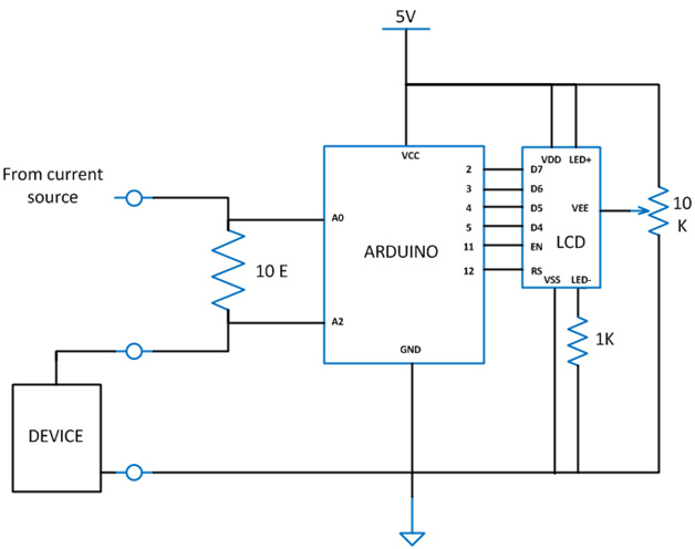
Circuit Diagram
The complete circuit diagram of the Arduino based Ammeter is given in which the device which consumes current comes in series with the resistor ‘R’, whose value is 10 ohms.
Code Description
The code continuously read the ADC channels A0 and A2 one after the other, each time calculating the values of V1 and V2.Whenboth the values of V1 and V2 are obtained, the code then calculates the value of current flowing through the device and the current consumption value is displayed on the 16*2 LCD.
The code running in the Arduino used the library function analogRead() to obtain the ADC value and lcd.print() to display the data on 16*2 LCD.

Fig. 7: Flowchart of Arduino Code for measuring current
Limitations:
The 10 ohm resistor is a high value compared to 0.05 ohm precision resistor inside a multi-meter. More current flow more voltage get drop across the resistor, and that voltage drop is proportional to value of resistance. For current values above 500mA measurement, create a low resistance by connecting as many resistances in parallel as possible. Since the ADC of Arduino can read a maximum of 5V only, don’t use a current source with voltage more than 5V.
Project Source Code
###
// include the library code:
#include <LiquidCrystal.h>
// initialize the library with the numbers of the interface pins
LiquidCrystal lcd(12, 11, 5, 4, 3, 2);
int adc_value = 0;
int voltage_peak_value = 0;
float voltage_average_value = 0;
float dc_voltage_V0 = 0;
float ac_voltage_V0 = 0;
float dc_voltage_V1 = 0;
float ac_voltage_V1 = 0;
float dc_current_I0 = 0;
float ac_current_I0 = 0;
unsigned long resistance;
unsigned long sample_count = 0;
void setup()
{
// set up the LCD's number of columns and rows:
lcd.begin(16, 2);
// Print a message to the LCD.
lcd.print(" EG LABS ");
pinMode(13, OUTPUT);
}
void loop()
{
// Serial.println("=============================== VOLTAGE ========================================");
voltage_peak_value = 0;
for(sample_count = 0; sample_count < 5000; sample_count ++)
{
adc_value = analogRead(A0);
if(voltage_peak_value < adc_value)
voltage_peak_value = adc_value;
else;
delayMicroseconds(10);
}
dc_voltage_V0 = voltage_peak_value * 0.00488;
ac_voltage_V0 = dc_voltage_V0 / 1.414;
//================================ CURRENT ========================================
voltage_peak_value = 0;
for(sample_count = 0; sample_count < 5000; sample_count ++)
{
adc_value = analogRead(A2);
if(voltage_peak_value < adc_value)
voltage_peak_value = adc_value;
else;
delayMicroseconds(10);
}
dc_voltage_V1 = voltage_peak_value * 0.00488;
ac_voltage_V1 = dc_voltage_V1 / 1.414;
dc_current_I0 = (dc_voltage_V1 - dc_voltage_V0) * 100;
ac_current_I0 = (ac_voltage_V1 - ac_voltage_V0) * 100;
lcd.clear();
lcd.setCursor(0, 0);
lcd.print(dc_current_I0);
lcd.print(" mA");
//=================================================================================
delay(1000);
}
###
Circuit Diagrams
Project Video
Filed Under: Electronic Projects
Filed Under: Electronic Projects

Questions related to this article?
👉Ask and discuss on Electro-Tech-Online.com and EDAboard.com forums.
Tell Us What You Think!!
You must be logged in to post a comment.