Engineers Garage

  • Projects and Tutorials
    • Electronic Projects
      • 8051
      • Arduino
      • ARM
      • AVR
      • PIC
      • Raspberry pi
      • STM32
    • Tutorials
    • Circuit Design
    • Project Videos
    • Components
  • Articles
    • Tech Articles
    • Insight
    • Invention Stories
    • How to
    • What Is
  • News
    • Electronic Products News
    • DIY Reviews
    • Guest Post
  • Forums
    • EDABoard.com
    • Electro-Tech-Online
    • EG Forum Archive
  • Digi-Key Store
    • Cables, Wires
    • Connectors, Interconnect
    • Discrete
    • Electromechanical
    • Embedded Computers
    • Enclosures, Hardware, Office
    • Integrated Circuits (ICs)
    • Isolators
    • LED/Optoelectronics
    • Passive
    • Power, Circuit Protection
    • Programmers
    • RF, Wireless
    • Semiconductors
    • Sensors, Transducers
    • Test Products
    • Tools
  • EE Resources
    • DesignFast
    • LEAP Awards
    • Oscilloscope Product Finder
    • White Papers
    • Webinars
  • EE Learning Center
    • Design Guides
      • WiFi & the IOT Design Guide
      • Microcontrollers Design Guide
      • State of the Art Inductors Design Guide
  • Women in Engineering

DIY Circuit Design: Audio Mixer

By Ashutosh Bhatt


The different sounds in songs like the sound of the guitar, drums, the voice of the singer etc. are recorded as separate tracks using separate microphones. More than 10 numbers of tracks are very common in normal quality songs. The audio mixer circuits find its applications in both recording and playback side. When recording a song the audio mixer circuits are used to mix two or more different sounds into a single track. The audio mixer devices used by the DJs for playing songs are familiar to most of the people.

This article discusses about the design of a simple audio mixer circuit. An op-amp based summing amplifier is used here to mix two sounds. The audio mixing is demonstrated with the help of mixing a high frequency musical sound with a low frequency bass beat, where the musical sound is generated by a musical IC and the bass beat played at a mobile phone and is captured and amplified through a microphone and amplifier circuits. 
DESCRIPTION
This audio mixer circuit uses two stage amplifiers with a microphone to capture and amplify the bass beats played on an external device so that it should have enough loudness when mixing with other sounds. A music generator IC is used to produce high frequency musical sound which will be then mixed with the audio mixing circuit. The audio mixing circuit alone is a very simple summing amplifier made with an op-amp.
Block Diagram of Audio Mixer Circuit
Fig. 1: Block Diagram of Audio Mixer Circuit
MICROPHONE COUPLER
The microphone coupler is a circuit which helps to couple out the weak audio signals generated at the microphone. There are different kinds of microphones which have different working principle, but all of them have a diaphragm which vibrates according to the sound signals. As the diaphragm vibrates the current flowing through the microphone varies according to the sound signals amplitude which made the diaphragm to vibrate. Here in this circuit a condenser microphone is used which and the varying current is made to flow through a resistor across which the equivalent voltage get generated due to the current flow. This voltage across the resistor will be having a DC voltage on to which the varying voltage gets added up. This varying voltage is separated out from the DC voltage with the help of a coupling capacitor and fed to the following amplifier circuits.
With a condenser microphone a 10K resistor and a 0.1uF coupling capacitor is used in most of the circuits.
Circuit Diagram of Condenser Mircophone Coupler
Fig. 2: Circuit Diagram of Condenser Mircophone Coupler
TWO STAGE AMPLIFIER
Here a single transistor based amplifier circuit is used as the first stage amplifier for the audio signals coupled out from the microphone. This circuit is designed to have extremely high gain so that the audio signals are get amplified enough. The transistor is connected in a common emitter configuration and fixed bias technique is used for biasing the transistor.

Circuit Diagram of Single Transistor Based Amplifier

Fig. 3: Circuit Diagram of Single Transistor Based Amplifier

The volume controller used here in between the transistor stages is a simple potentiometer, which will attenuate the output of the first stage amplifier before it is fed to the second stage amplifier. This volume controller circuit helps to keep the amplitude of the signal within the input range of the second stage amplifier circuit.
The second stage amplifier is exactly similar in design with the first stage amplifier. This amplifier simply amplifies the signal more and at the output of this stage one can obtain a good enough voltage amplified signal which is ready to be current amplified by the following current amplifier circuit.
Circuit Diagram of Second Stage Transistor Based Amplifier with potentiometer
Fig. 4: Circuit Diagram of Second Stage Transistor Based Amplifier with Potentiometer
Current Amplifer Circuit on Breadboard
Fig. 5: Current Amplifer Circuit on Breadboard

Music Generator, Summing Amplifier

MUSIC GENERATOR
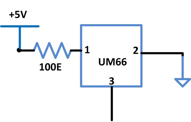
The music generated in this circuit with the help of a versatile musical IC UM66. This IC can works in the voltage range of 1.5V to 4.5V. The IC has three pins and the first pin is where the supply voltage is applied and the second pin is connected to the ground and the third pin produces a musical output signal.
Since the maximum voltage rating of the IC is only 4.5V, A 100 ohm resistor is connected between the first pin and the 5V power supply, which will produces a voltage drop when the current flows through it and hence maintain the voltage at the first pin at less than 4.5V.
Circuit Diagram of Music Generator IC UM66
Fig. 6: Circuit Diagram of Music Generator IC UM66
Musical IC UM66 Circuit on Breadboard
Fig. 7: Musical IC UM66 Circuit on Breadboard

SUMMING AMPLIFIER

The summing amplifier here is an op-amp based inverting amplifier designed to be having unity gain. This amplifier circuit has the feature of adding the different voltages applied at its inverting pin through separate equal valued input resistances connected at the inverting pin. A common 741 op-amp is used here as the summing amplifier of unity gain.
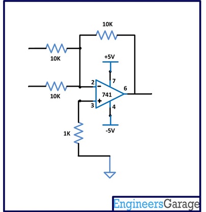
 Circuit Diagram Summing Amplifer

Fig. 8: Circuit Diagram of Summing Amplifier
Summing Amplifer Circuit on breadboard
Fig. 9: Summing Amplifier Circuit on Breadboard
Suppose if S1 and S2 are the two signals applied at the input of the above circuit, then the output of the circuit will be;
S1 + S2
Both the signals S1 and S2 will get equal amplification when reproduced at the output of the circuit.
This op-amp based amplifier circuit also provides enough current sourcing capability to the output signals and hence they can be directly applied to normal 8 ohm loudspeakers.
LOUDSPEAKER
The loudspeaker used here is a very common 8 ohm loudspeaker which can operate with a maximum power of 0.5W.
Circuit Diagram of Audio Mixer with 8 ohm Loudspeaker
Fig. 10 : Circuit Diagram of Audio Mixer with 8 ohm Loudspeaker
Circuit Diagram of Audio Mixer with Loudspeaker, Amplifier and Transistor
Fig. 11: Circuit Diagram of Audio Mixer with Loudspeaker, Amplifier and Transistor


Filed Under: Circuit Design


Questions related to this article?
👉Ask and discuss on EDAboard.com and Electro-Tech-Online.com forums.


Tell Us What You Think!! Cancel reply

You must be logged in to post a comment.

HAVE A QUESTION?

Have a technical question about an article or other engineering questions? Check out our engineering forums EDABoard.com and Electro-Tech-Online.com where you can get those questions asked and answered by your peers!


Featured Tutorials

  • Introduction to Brain Waves & its Types (Part 1/13)
  • Understanding NeuroSky EEG Chip in Detail (Part 2/13)
  • Performing Experiments with Brainwaves (Part 3/13)
  • Amplification of EEG Signal and Interfacing with Arduino (Part 4/13)
  • Controlling Led brightness using Meditation and attention level (Part 5/13)
  • Control Motor’s Speed using Meditation and Attention Level of Brain (Part 6/13)

Stay Up To Date

Newsletter Signup

Sign up and receive our weekly newsletter for latest Tech articles, Electronics Projects, Tutorial series and other insightful tech content.

EE Training Center Classrooms

EE Classrooms

Recent Articles

  • What are the battery-selection criteria for low-power design?
  • Key factors to optimize power consumption in an embedded device
  • EdgeLock A5000 Secure Authenticator
  • How to interface a DS18B20 temperature sensor with MicroPython’s Onewire driver
  • Introduction to Brain Waves & its Types (Part 1/13)

Most Popular

5G 555 timer circuit 8051 ai Arduino atmega16 automotive avr bluetooth dc motor display Electronic Part Electronic Parts Fujitsu ic infineontechnologies integratedcircuit Intel IoT ir lcd led maximintegratedproducts microchip microchiptechnology Microchip Technology microcontroller microcontrollers mosfet motor powermanagement Raspberry Pi remote renesaselectronics renesaselectronicscorporation Research samsung semiconductor sensor software STMicroelectronics switch Technology vishayintertechnology wireless

RSS EDABOARD.com Discussions

  • Atmega based inverter project.
  • Transistors dimension with changing CMOS technology.
  • Parts storage / inventory best practices and organization
  • Very low voltage/power Schmitt trigger?
  • Amplifier HX711 module

RSS Electro-Tech-Online.com Discussions

  • Disabled son needs advice please
  • RF modules which can handle high number of bytes per second
  • Question about ultrasonic mist maker
  • DIY bluetooth speaker
  • Pet Microchip scan
Engineers Garage
  • Analog IC TIps
  • Connector Tips
  • DesignFast
  • EDABoard Forums
  • EE World Online
  • Electro-Tech-Online Forums
  • Microcontroller Tips
  • Power Electronic Tips
  • Sensor Tips
  • Test and Measurement Tips
  • 5G Technology World
  • About Us
  • Contact Us
  • Advertise

Copyright © 2022 WTWH Media LLC. All Rights Reserved. The material on this site may not be reproduced, distributed, transmitted, cached or otherwise used, except with the prior written permission of WTWH Media
Privacy Policy | Advertising | About Us

Search Engineers Garage

  • Projects and Tutorials
    • Electronic Projects
      • 8051
      • Arduino
      • ARM
      • AVR
      • PIC
      • Raspberry pi
      • STM32
    • Tutorials
    • Circuit Design
    • Project Videos
    • Components
  • Articles
    • Tech Articles
    • Insight
    • Invention Stories
    • How to
    • What Is
  • News
    • Electronic Products News
    • DIY Reviews
    • Guest Post
  • Forums
    • EDABoard.com
    • Electro-Tech-Online
    • EG Forum Archive
  • Digi-Key Store
    • Cables, Wires
    • Connectors, Interconnect
    • Discrete
    • Electromechanical
    • Embedded Computers
    • Enclosures, Hardware, Office
    • Integrated Circuits (ICs)
    • Isolators
    • LED/Optoelectronics
    • Passive
    • Power, Circuit Protection
    • Programmers
    • RF, Wireless
    • Semiconductors
    • Sensors, Transducers
    • Test Products
    • Tools
  • EE Resources
    • DesignFast
    • LEAP Awards
    • Oscilloscope Product Finder
    • White Papers
    • Webinars
  • EE Learning Center
    • Design Guides
      • WiFi & the IOT Design Guide
      • Microcontrollers Design Guide
      • State of the Art Inductors Design Guide
  • Women in Engineering