You may have seen many projects of generating different colours from RGB LED using Arduino. The given project also generates different colours from RGB LED using Arduino. But also, it displays the amount of red, green and blue colour on LCD.
We know, all colours are basically mixing of three primary colours RED, GREEN and BLUE in different amount. For example, by mixing RED and GREEN colour, we can generate YELLOW and by varying their amount we can generate different colours like ORANGE, LEMON GREEN etc many other colours. Also, we can get different shades of RED and GREEN.
So here, in this project, I am generating different colours and shades using RGB LED using Arduino and 3 potentiometers. We can vary the intensity of red, green and blue colour of RGB LED by applying variable pulse width input – PWM. As the width of applied pulse increases the colour intensity increases and vice versa. The Arduino board is used to generate PWM signal that is applied to RGB LED. It also displays the pulse width applied to red, green and blue LED on LCD to show the intensity of colour as a % between 0 to 100.
CIRCUIT DESCRIPTION
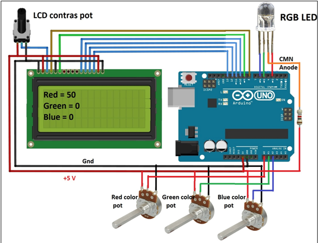
• The fix terminals of pots are connected to +5V and ground of Arduino board as shown. The middle – sliding terminals of all three pots are connected to analog input pins A0, A1 and A2 of Arduino board
• The three terminals of RGB LED, red, green and blue are connected with analog output pins 3, 4 and 5 respectively. The common anode terminal is given 5 V through current limiting resistor
• Data pins D4 – D7 of LCD are connected to digital pins 10, 11, 12 and 13 of board. LCD control pins Rs and En are connected to pins 8 and 9 respectively. One more control pin RW (of LCD) is connected to ground to make LCD write enable always
• One pot is connected to LCD contras control pin VEE to vary its contras
• Complete circuit is given supply from Arduino board through USB of PC / laptop
Here is the snap of circuit arrangement.

Fig. 1: Prototype of Arduino based RGB LED Color Generator
CIRCUIT OPERATION
• When circuit is given power supply, initially, the message is displayed on LCD as “”
• Then LCD displays the intensity of Red, Green and Blue colour in RGB LED
• The colour intensity can be varied by three pots given – one for each colour. The intensity can be varied from 0 to 255
• When any of the pot is varied, it will vary the analog input voltage from 0 to 5 V to analog input pin of Arduino
• The Arduino will read this analog input voltage and gives corresponding digital value between 0 to 1023
• This value is used to control the analog output – the width of the pulse, applied to RGB LED. The pulse width is varied from 0 – 100% as per the analog output of 0 to 255
• As the pot is varied from min to max the analog input voltage varies from 0 to 5 V. the pulse width at analog output increases from 0 to 100%. The LCD displays this value as 0 to 255 and this increases the colour intensity from 0 to 100%
• For example if green colour pot is varied, the pulse width at analog output pin 5 is varied so green colour intensity is varied and on LCD it is displayed as Green colour varied between 0 to 255
• Thus by varying and setting different values in all 3 pots we can set the intensity of red, green and blue colour in RGB LED and with the combinations of these 3 colours we can generate different colours
SOFTWARE PROGRAM
The circuit operation is completely based on the program embedded into Arduino board micro controller ATMega328. The program is responsible to perform following tasks – :
• Reads analog voltage input one by one from pots
• Convert this analog value into digital value between 0 to 1023
• Vary the pulse width at 3 analog outputs corresponding to red, green and blue LED
• Vary the red, green and blue colour intensity from 0 – 100% as per the respective value of red-green-blue pot
• Display the red-green-blue colour amount on LCD between 0 – 255
The program is edited and compiled in to Arduino IDE and it is uploaded to Arduino board using USB programmer. Here is the program code written in arduino C language.
Project Source Code
###
#include <LiquidCrystal.h> #define red_led 3 #define green_led 5 #define blue_led 6 LiquidCrystal lcd(8,9,10,11,12,13); int red,green,blue,R,G,B; void setup() { lcd.begin(16, 4); lcd.clear(); lcd.print("Set RGB values "); lcd.setCursor(0,1); lcd.print("using 3 pots"); delay(3000); lcd.clear(); lcd.print("Red = "); lcd.setCursor(0,1); lcd.print("Green = "); lcd.setCursor(0,2); lcd.print("Blue = "); } void loop() { // put your main code here, to run repeatedly: red = analogRead(A0); green = analogRead(A1); blue = analogRead(A2); lcd.setCursor(6,0); lcd.print(red/4); lcd.setCursor(8,1); lcd.print(green/4); lcd.setCursor(7,2); lcd.print(blue/4); R = 255 - (red/4); analogWrite(red_led,R); G = 255 - (green/4); analogWrite(green_led,G); B = 255 - (blue/4); analogWrite(blue_led,B); }###
Circuit Diagrams
Project Video
Filed Under: Electronic Projects
Filed Under: Electronic Projects

Questions related to this article?
👉Ask and discuss on Electro-Tech-Online.com and EDAboard.com forums.
Tell Us What You Think!!
You must be logged in to post a comment.