D flip-flop is used to store 1-bit information. It is called 1-bit register and stores 1-bit information when a clock pulse is applied. Actually, it latches the input to output when the clock is applied. It’s widely used in memory storage devices.
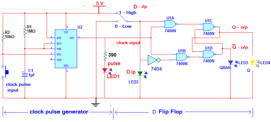
Here, the given circuit demonstrates the operation of D flip-flop. The flip-flop is built using four 2 input NAND gates, one NOT gate and clock pulse generator is built using multivibrator chip IC NE555. SPDT switch is used to give D input as logic 1 (high – 5 V) and logic 0 (low – 0 V). Different color LEDs are used for input-output logic indications. Please refer the table given below.

Fig. 1: Table listing LED Statuses for Logic Levels of 555 IC based D Flip-Flop
The circuit is very easy to build and all the components are also easily available and cheap. Here is the list of required components.

Fig. 2: List of Components required for 555 IC based D Flip-Flop
The circuit can be built on general purpose PCB or breadboard. So let us see the circuit diagram followed by its description and operation.
CIRCUIT DESCRIPTION
The complete circuit is divided into two different sections -:
1. Clock pulse generator circuit
2. D flip-flop circuit
Clock pulse generator circuit is built using IC NE555. IC NE555 is wired in monostable mode. Timing components R1 and C1 are chosen such as to give pulse output of 1 sec approx. A push button is connected to trigger input pin 2. The output of IC is given as clock pulse input to the flip-flop circuit. One LED is connected (LED1) to this output to indicate clock pulse output from the circuit.
D flip-flop circuit is built using quad 2 input NAND gate chip 74LS00 and NOT gate chip 74LS04. The circuit consist of four 2 input NAND gates, one NOT gate, one SPDT switches for input and 3 LEDs for output-input indications. The SPDT switches provide logic 1 (high) or logic 0 (low) to D input. The status of D input is indicated by the green LED LED2. The Q and QBAR outputs of the flip-flop are connected to two red LEDs LED3 and LED4 as shown. The complete circuit works on 5 V supply.
Here is the snap of circuit arrangement.

Fig. 3: Prototype of 555 IC based D Flip-Flop
CIRCUIT OPERATION
Clock pulse generation circuit – because IC Ne555 is wired in the monostable mode it will generate 1 sec pulse every time when a trigger input is applied by pressing push button. The LED blinks to indicate clock pulse is generated.
D flip-flop circuit – the circuit works as per following truth table.

Fig. 4: Truth Table of 555 IC based D Flip-Flop
First, D is given logic 1 input and from SPDT switch. Now when the clock pulse is given from clock pulse generator circuit, the two inputs of U1A gate become high (logic 1). So as per NAND gate operation* its output goes low (logic 0). As this output is connected to one input of U1C, the output of U1C becomes high immediately as per NAND gate truth table*. The Q output is high and LED4 glows. This output is given as input to U1D. Another input to U1D is from U1B and that is also high because it is given inverted D input that is 0. So now, as both the inputs of U1D are high, its output will go low. Thus QBAR output is low and LED3 is off.
Thus every time when the clock pulse is applied the D input is latched into Q output as logic 1 or logic 0 and this is the operation of D flip-flop.
*NAND gate truth table

Fig. 5: Truth Table of NAND Gate
Circuit Diagrams
Project Video
Filed Under: Electronic Projects
Filed Under: Electronic Projects

Questions related to this article?
👉Ask and discuss on EDAboard.com and Electro-Tech-Online.com forums.
Tell Us What You Think!!
You must be logged in to post a comment.