Engineers Garage

  • Electronic Projects & Tutorials
    • Electronic Projects
      • Arduino Projects
      • AVR
      • Raspberry pi
      • ESP8266
      • BeagleBone
      • 8051 Microcontroller
      • ARM
      • PIC Microcontroller
      • STM32
    • Tutorials
      • Audio Electronics
      • Battery Management
      • Brainwave
      • Electric Vehicles
      • EMI/EMC/RFI
      • Hardware Filters
      • IoT tutorials
      • Power Tutorials
      • Python
      • Sensors
      • USB
      • VHDL
    • Circuit Design
    • Project Videos
    • Components
  • Articles
    • Tech Articles
    • Insight
    • Invention Stories
    • How to
    • What Is
  • News
    • Electronic Product News
    • Business News
    • Company/Start-up News
    • DIY Reviews
    • Guest Post
  • Forums
    • EDABoard.com
    • Electro-Tech-Online
    • EG Forum Archive
  • DigiKey Store
    • Cables, Wires
    • Connectors, Interconnect
    • Discrete
    • Electromechanical
    • Embedded Computers
    • Enclosures, Hardware, Office
    • Integrated Circuits (ICs)
    • Isolators
    • LED/Optoelectronics
    • Passive
    • Power, Circuit Protection
    • Programmers
    • RF, Wireless
    • Semiconductors
    • Sensors, Transducers
    • Test Products
    • Tools
  • Learn
    • eBooks/Tech Tips
    • Design Guides
    • Learning Center
    • Tech Toolboxes
    • Webinars & Digital Events
  • Resources
    • Digital Issues
    • EE Training Days
    • LEAP Awards
    • Podcasts
    • Webinars / Digital Events
    • White Papers
    • Engineering Diversity & Inclusion
    • DesignFast
  • Guest Post Guidelines
  • Advertise
  • Subscribe

DIY: Digital IC Tester

By Mohit Mishra July 2, 2014

Most of the engineering students who study digital logic design use digital logic IC’s in the lab as well as outside the lab in their  projects and other applications.
 
Sometimes while soldering these IC’s on the board, you may not get the proper output which would make you think whether it’s working properly or not.  In such a case,  it would be very  impractical to sit down and check each IC with the help of  LED and power supply.
 
The question is how will you do it in an effective way?
The answer to this question is simple, you don’t have to. Leave this work to microcontroller and a couple lines of code.
 
This is a project based on arm7 microcontroller, which tests the 74xx series IC. The coding includes testing of 7400, 7402, 7404, 7408, 7432, 7486 IC. It can be extended further based on the need.

This includes an extra board  with IC holder which holds the IC’s  that are to be tested.  It also includes some push button which tells the system which IC is being tested. For this, you just have to put in the IC and press the relative button to test  it. 
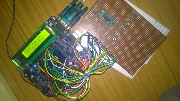
Prototype of LPC2148 ARM Microcontroller based Digital IC Tester

Fig. 1: Prototype of LPC2148 ARM Microcontroller based Digital IC Tester

Application:

This is very useful for testing the digital logic IC’s as there are multiple gates in each one of them and those are to be tested one at a time. In some cases we can have up to six gates, while in other cases we may have IC which takes up to 3 input.  It saves time and human effort for testing the  IC giving out the result instantaneously.
 
This includes an arm7 microcontroller (LPC2148), boards for the placement of test IC, and an LCD which displays the result.
 

The IC is placed in holder and the switch is pressed. Then a set of input is given to  its input pin and it observes the output pins.the output pins.

Image showing soldering on LPC2148 ARM Microcontroller board

Fig. 2: Image showing soldering on LPC2148 ARM Microcontroller board

BLOCK DIAGRAM:
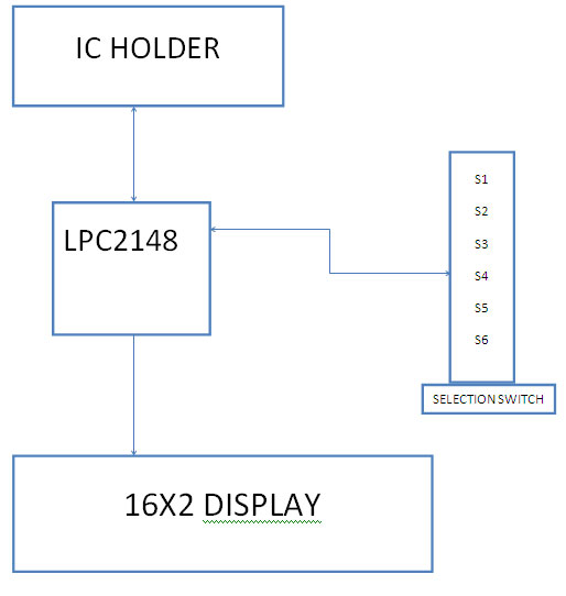
Overview of LPC2148 ARM Microcontroller based Digital IC Tester

Fig. 3: Overview of LPC2148 ARM Microcontroller based Digital IC Tester

Components & Working

IC HOLDER:

The IC is put onto the holder, locked and then the switch is pressed. Its purpose is to hold the  IC in place during testing.


ARM LPC2148:

This is the heart of project and all the process is happening here itself. The features of this microcontroller are as follows.
 
FEATURES
 
• 16-bit/32-bit ARM7TDMI-S microcontroller in a tiny LQFP64 package.
 
• 40 kB of on-chip static RAM and 512 kB of on-chip flash memory.
 
• In-System Programming/In-Application Programming (ISP/IAP) via on-chip boot loader software.
 
• Embedded ICE RT and Embedded Trace interfaces offer real-time debugging with the on-chip Real Monitor software and high-speed tracing of instruction execution.
 
• USB 2.0 Full-speed compliant device controller with  2KB of endpoint RAM.
 
• Embedded ICE RT and Embedded Trace interfaces offer real-time debugging with the on-chip Real Monitor software and high-speed tracing of instruction execution.
 
• USB 2.0 Full-speed compliant device controller with  2KB of endpoint RAM.
 
• Two 10-bit ADCs provide a total of 14 analog inputs.
 
• Single 10-bit DAC provides variable analog output.
 
• Two 32-bit timers/external event counters (with four capture and four Compare channels each), PWM unit (six outputs) and watchdog.
 
• Low power Real-Time Clock (RTC) with independent power and 32 kHz clock input.
 
• Multiple serial interfaces including two UARTs, two Fast I²C-bus (400 Kbit/s), SPI and SSP with buffering and variable data length capabilities.
 
• Vectored Interrupt Controller (VIC) with configurable priorities and vector addresses.
 
• Up to 45 of 5 V tolerant fast general purpose I/O pins in a tiny LQFP64 package.
 
• 60 MHz maximum CPU clock available from programmable on-chip PLL with settling time of 100 us.
 
• On-chip integrated oscillator operates with an external crystal from 1 MHz to 25 MHz
 
• Power saving modes include- Idle and Power-down.
 
• Conversion time for  ADC is >=2.4us
 

LCD DISPLAY:

LCD (Liquid Crystal Display) screen is an electronic display module  that finds a wide range of applications. A 16×2 LCD display is very basic module and commonly used in various devices and circuits. These modules are preferred over seven segments and other multi segment LEDs. The reasons being: LCDs are economical; easily programmable; have no limitation of displaying special & even custom characters (unlike in seven segments), animations and so on.
 
A 16×2 LCD means it can display 16 characters per line and there are 2 such lines. In this LCD each character is displayed in 5×7 pixel matrix. This LCD has two registers namely, Command and Data.

The command register stores the command instructions given to the LCD. A command is an instruction given to LCD to do a predefined task like initializing it, clearing its screen, setting the cursor position, controlling display etc. The data register stores data to be displayed on the LCD. The data is the ASCII value of the character to be displayed on the LCD. Click to learn more about internal structure of an LCD.


WORKING:

Image showing LPC ARM Microcontroller based Digital IC Tester designed on PCB

Fig. 4: Image showing LPC ARM Microcontroller based Digital IC Tester designed on PCB

Keep the ic in place and press the relative key,  this gives the input to  its pins and reads the output.  It’s done by making pins which are connected to input pins to high and then observing the output.
 
To do this, read the data from io0pin register and take the operation which removes the data of bits unrelated to the output pins.  Match  the data to the pre stored value and if it comes out true then IC is good else it is bad and not useable.
 

MICROCONTROLLER BOARD:

I have been using ngx blue board which has core of arm lpc 2148.
 
The specifications are as follows.
 
• Dimensions: 127 X 127 mm2
 
• Two layer PCB (FR-4 material)
 
• Power: DC 6.5V with power LED On-board linear regulators generate +3.3V/500mA and +5V/500mA from power supply USB connector (as alternate power source)
 
• ISP and reset switch
 
• 12.0000 MHz crystal for MCU,32Khz crystal for RTC
 
• Extension headers for all microcontroller pins
 
• RS232 connector (2x), VGA connector, PS2 connector, 20pin – JTAG connector, SD/MMC card connector, USB type-B connector with link-LED
 
• All peripheral configurable via jumper
 
• Audio power amplifier
 
• 2 line X 16 character LCD
 
• Backlight control for LCD
 
• Configurable for manual and automatic program download (ISP) via serial port
 
• Two layer PCB (FR-4 material)
 
• 8 controllable LEDs on SPI


Project Source Code

###


#include <LPC214x.H>                       /* LPC214x definitions */
#include "lcd.h"
#define LCD_BACK_LIGHT_TIMEOUT 1000
#define LCD_BACKLIGHT (1 << 21)
#define LCD_BACK_LIGHT_DIR IO1DIR
#define LCD_BACK_LIGHT_SET IO1SET
#define LCD_BACK_LIGHT_CLR IO1CLR
#define LCD_DATA_DIR    IO0DIR
#define LCD_DATA_SET    IO0SET
#define LCD_DATA_CLR    IO0CLR
#define LCD_CTRL_DIR    IO1DIR
#define LCD_CTRL_SET       IO1SET
#define LCD_CTRL_CLR       IO1CLR
#define LCDRS            (1 << 24)
#define LCDRW            (1 << 23)
#define LCDEN            (1 << 22)
#define LCD_D4 (1 << 10)
#define LCD_D5 (1 << 11)
#define LCD_D6 (1 << 12)
#define LCD_D7 (1 << 13)
#define LCD_DATA_MASK           (LCD_D4 | LCD_D5 | LCD_D6 | LCD_D7)
#define LCD_BUSY_FLAG           LCD_D7
#define LCD_CONTROL_MASK        0x01C00000
/**
**************************************************************************
****1111
  Function Name : delay()
  Description :This function suspends the tasks for specified ticks. 
  Input :  ticks:no of ticks in multiple of 1 usec
            task: task to be suspended
  Output : void
  Note :
*******************************************************************************
*/
void delay(int count)
{
  int j=0,i=0;
  for(j=0;j<count;j++)
  {
    /* At 60Mhz, the below loop introduces
    delay of 10 us */
    for(i=0;i<35;i++);
  }
}
/**
********************************************************************************************
  Function Name : wait_lcd()
  Description   : 
  Input         : 
  Output        : Void
  Note          :
********************************************************************************************
*/
void wait_lcd( void )
{
  LCD_CTRL_CLR |=  LCDRS; 
  LCD_CTRL_SET |=  LCDRW |LCDEN;
  while(IO1PIN & LCD_BUSY_FLAG); /* wait for busy flag to become low */
  LCD_CTRL_CLR |= LCDEN | LCDRW;
  LCD_DATA_DIR |= LCD_DATA_MASK;
  delay(100);  
}
/**
********************************************************************************************
  Function Name : lcd_command_write()
  Description   : 
  Input         : 
  Output        : Void
  Note          :
********************************************************************************************
*/
void lcd_command_write( unsigned char command )
{
  unsigned char temp=0;
  unsigned int temp1=0;
  temp=command;
  temp=(temp>>4)&0x0F;
  temp1=(temp<<10)&LCD_DATA_MASK;
  LCD_CTRL_CLR = LCDRS;
  LCD_CTRL_SET = LCDEN;
  LCD_DATA_CLR = LCD_DATA_MASK;
  LCD_DATA_SET = temp1;
  delay(10000);
  LCD_CTRL_CLR = LCDEN;
  temp=command;
  temp&=0x0F;
  temp1=(temp<<10)&LCD_DATA_MASK;
  delay(100*2);
  LCD_CTRL_CLR |= LCDRS;
  LCD_CTRL_SET |= LCDEN;
  LCD_DATA_CLR = LCD_DATA_MASK;
  LCD_DATA_SET = temp1;
  delay(10000); 
  LCD_CTRL_CLR |= LCDEN;
  wait_lcd();
}
/**
********************************************************************************************
  Function Name : set_lcd_port_output()
  Description   : 
  Input         : 
  Output        : Void
  Note          :
********************************************************************************************
*/
void set_lcd_port_output( void )
{
  LCD_CTRL_DIR |= ( LCDEN | LCDRS | LCDRW );
  LCD_CTRL_CLR |= ( LCDEN | LCDRS | LCDRW ); 
  LCD_DATA_DIR |= LCD_DATA_MASK;
}
/* *
********************************************************************************************
  Function Name : lcd_clear()
  Description   : 
  Input         : 
  Output        : Void
  Note          :
********************************************************************************************
*/
void lcd_clear( void)
{
  lcd_command_write( 0x01 );
}
/**
********************************************************************************************
  Function Name : lcd_gotoxy()
  Description   : 
  Input         : 
  Output        : Void
  Note          :
********************************************************************************************
*/
int lcd_gotoxy( unsigned int x, unsigned int y)
{
  int retval = 0;
  if( (x > 1) && (y > 15) )
  {
   retval = -1;
  }
 else
 {
  if( x == 0 )
  {
    lcd_command_write( 0x80 + y ); /* command - position cursor at 0x00 (0x80 + 0x00 ) */
  }
 else if( x==1 )
{
    lcd_command_write( 0xC0 + y ); /* command - position cursor at 0x40 (0x80 + 0x00 ) */
    }
   }
   return retval;
}
/**
********************************************************************************************
  Function Name : lcd_data_write()
  Description   : 
  Input         : 
  Output        : Void
  Note          :
********************************************************************************************
*/
void lcd_data_write( unsigned char data )
{
  unsigned char temp=0;
  unsigned int temp1=0;
  temp=data;
  temp=(temp>>4)&0x0F;
  temp1=(temp<<10)&LCD_DATA_MASK;
  LCD_CTRL_SET |= LCDEN|LCDRS;
  LCD_DATA_CLR = LCD_DATA_MASK;
  LCD_DATA_SET = temp1;
  LCD_CTRL_CLR |= LCDEN;
  temp=data;
  temp&=0x0F;
  temp1=(temp<<10)&LCD_DATA_MASK;
  LCD_CTRL_SET |= LCDEN|LCDRS;
  LCD_DATA_CLR = LCD_DATA_MASK;
  LCD_DATA_SET = temp1;
  LCD_CTRL_CLR |= LCDEN;
  wait_lcd();
}
/**
********************************************************************************************
  Function Name : lcd_putchar()
  Description   : 
  Input         : 
  Output        : Void
  Note          :
*******************************************************************************************
*/
void lcd_putchar( int c )
{
  lcd_data_write( c );
}
/**
********************************************************************************************
  Function Name : lcd_putstring()
  Description   : 
  Input         : 
  Output        : Void
  Note          :
********************************************************************************************
*/
void lcd_putstring( unsigned char line, char *string )
{
  unsigned char len = MAX_CHAR_IN_ONE_LINE;
  lcd_gotoxy( line, 0 );
  while(*string != '' && len--)
  {
    lcd_putchar( *string );
    string++;
  }
}

/**
********************************************************************************************
  Function Name : lcd_backlight_on()
  Description   : 
  Input         : 
  Output        : Void
  Note          :
********************************************************************************************
*/
void lcd_backlight_on()
{    
  LCD_BACK_LIGHT_DIR |= LCD_BACKLIGHT;
  LCD_BACK_LIGHT_SET |= LCD_BACKLIGHT; 
}
/**
********************************************************************************************
 Function Name : turn_off_lcd_back_light()
 Description   : 
 Input         : 
 Output        : Void
 Note          :
********************************************************************************************
*/
void turn_off_lcd_back_light_cb(void)
{
  LCD_BACK_LIGHT_DIR |= LCD_BACKLIGHT;
  LCD_BACK_LIGHT_CLR |= LCD_BACKLIGHT;
}
/**
********************************************************************************************
  Function Name : init_lcd()
  Description   : 
  Input         : 
  Output        : Void
  Note          :
********************************************************************************************
*/
void init_lcd( void )
{
  set_lcd_port_output();
  delay(100*100);
  lcd_command_write(0x28);     /*   4-bit interface, two line, 5X7 dots.        */
  lcd_clear() ;                /*   LCD clear                                   */
  lcd_command_write(0x02);     /*   cursor home                                 */
  lcd_command_write(0x06);     /*   cursor move direction                       */
  lcd_command_write(0x0C) ;    /*   display on      */
  lcd_gotoxy(0, 0);
  lcd_clear(); 
  lcd_putstring(0,"PRESS THE KEY");
  lcd_putstring(1,"FOR SELECTION");
}


LCD.H


#ifndef _LCD_H
#define _LCD_H
#define MAX_CHAR_IN_ONE_LINE 16
enum ROW_NUMBERS
{
  LINE1,
  LINE2 
};
void init_lcd(void);
void lcd_putstring(unsigned char line, char *string);
void lcd_clear(void);
void lcd_backlight_on(void);
int lcd_gotoxy(unsigned int x, unsigned int y);
void lcd_putchar(int c);
#endif
###


Circuit Diagrams

Circuit-Diagram-Lpc2148-Arm-Microcontroller-Based-Digital-Ic-Tester


Filed Under: Electronic Projects
Tagged With: arm, LPC2148
 

Next Article

← Previous Article
Next Article →

Questions related to this article?
👉Ask and discuss on EDAboard.com and Electro-Tech-Online.com forums.


Tell Us What You Think!! Cancel reply

You must be logged in to post a comment.

EE TECH TOOLBOX

“ee
Tech Toolbox: 5G Technology
This Tech Toolbox covers the basics of 5G technology plus a story about how engineers designed and built a prototype DSL router mostly from old cellphone parts. Download this first 5G/wired/wireless communications Tech Toolbox to learn more!

EE Learning Center

EE Learning Center
“engineers
EXPAND YOUR KNOWLEDGE AND STAY CONNECTED
Get the latest info on technologies, tools and strategies for EE professionals.

HAVE A QUESTION?

Have a technical question about an article or other engineering questions? Check out our engineering forums EDABoard.com and Electro-Tech-Online.com where you can get those questions asked and answered by your peers!


RSS EDABOARD.com Discussions

  • Finding past posts on edaboard?
  • I think i have devised a new type of "super_transformer" for the Electricity grid?
  • Industrial Relay Board Design for Motorcycle Use
  • sequence detector FSM design
  • Need suggestions in task NI6363 retrigger (analog trigger)

RSS Electro-Tech-Online.com Discussions

  • Sump pit water alarm - Kicad 9
  • Pic18f25q10 osccon1 settings swordfish basic
  • Anyone jumped from Easyeda std to Easyeda pro?
  • turbo jet fan - feedback appreciated.
  • More fun with ws2812 this time XC8 and CLC

Featured – LoRa/LoRaWan Series

  • What is the LoRaWAN network and how does it work?
  • Understanding LoRa architecture: nodes, gateways, and servers
  • Revolutionizing RF: LoRa applications and advantages
  • How to build a LoRa gateway using Raspberry Pi
  • How LoRa enables long-range communication
  • How communication works between two LoRa end-node devices

Recent Articles

  • How IoT network topologies work
  • The top five AI startups to watch in 2025
  • STMicroelectronics unveils SoC based on secure MCU
  • Nexperia’s 48 V ESD diodes support higher data rates with ultra-low capacitance design
  • Taoglas releases Patriot antenna with 18 integrated elements covering 600 to 6000 MHz

EE ENGINEERING TRAINING DAYS

engineering

Submit a Guest Post

submit a guest post
Engineers Garage
  • Analog IC TIps
  • Connector Tips
  • Battery Power Tips
  • DesignFast
  • EDABoard Forums
  • EE World Online
  • Electro-Tech-Online Forums
  • EV Engineering
  • Microcontroller Tips
  • Power Electronic Tips
  • Sensor Tips
  • Test and Measurement Tips
  • 5G Technology World
  • Subscribe to our newsletter
  • About Us
  • Contact Us
  • Advertise

Copyright © 2025 WTWH Media LLC. All Rights Reserved. The material on this site may not be reproduced, distributed, transmitted, cached or otherwise used, except with the prior written permission of WTWH Media
Privacy Policy

Search Engineers Garage

  • Electronic Projects & Tutorials
    • Electronic Projects
      • Arduino Projects
      • AVR
      • Raspberry pi
      • ESP8266
      • BeagleBone
      • 8051 Microcontroller
      • ARM
      • PIC Microcontroller
      • STM32
    • Tutorials
      • Audio Electronics
      • Battery Management
      • Brainwave
      • Electric Vehicles
      • EMI/EMC/RFI
      • Hardware Filters
      • IoT tutorials
      • Power Tutorials
      • Python
      • Sensors
      • USB
      • VHDL
    • Circuit Design
    • Project Videos
    • Components
  • Articles
    • Tech Articles
    • Insight
    • Invention Stories
    • How to
    • What Is
  • News
    • Electronic Product News
    • Business News
    • Company/Start-up News
    • DIY Reviews
    • Guest Post
  • Forums
    • EDABoard.com
    • Electro-Tech-Online
    • EG Forum Archive
  • DigiKey Store
    • Cables, Wires
    • Connectors, Interconnect
    • Discrete
    • Electromechanical
    • Embedded Computers
    • Enclosures, Hardware, Office
    • Integrated Circuits (ICs)
    • Isolators
    • LED/Optoelectronics
    • Passive
    • Power, Circuit Protection
    • Programmers
    • RF, Wireless
    • Semiconductors
    • Sensors, Transducers
    • Test Products
    • Tools
  • Learn
    • eBooks/Tech Tips
    • Design Guides
    • Learning Center
    • Tech Toolboxes
    • Webinars & Digital Events
  • Resources
    • Digital Issues
    • EE Training Days
    • LEAP Awards
    • Podcasts
    • Webinars / Digital Events
    • White Papers
    • Engineering Diversity & Inclusion
    • DesignFast
  • Guest Post Guidelines
  • Advertise
  • Subscribe