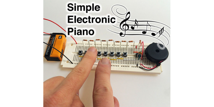
Electronics can produce sounds quite easily with a few parts. In this bog we are sharing a simple way to create a piano with a 555 timer. The maker designed as well as tested the circuit with 123D Circuits and created the original device. The hardware or raw materials needed in this task include a 555 timer, 8 pushbuttons, a 100nF capacitor, an assorted resistor, a piezo buzzer, 22AWG hookup wire, a 9V battery connector, a solderless breadboard, a 9V battery.
The creation of this musical instrument involves some tricky mathematics. The piano involves an astable mode of common 555 timer integrated with a circuit that will generate sound that drives the speaker. Every musical note bears a prime frequency, it refers to the specific number of times a thing vibrates when it produces a particular sound. The frequency of sound generated by 555 timer in the astable mode depends on the Capacitor © values along with 2 resistors (RA and RB). the relationship goes as “frequency = 1/.7(RA+RB) C. In this specific instrument, the values of RA and C are same for all notes. This means, only RB is left out for producing the sounds. Therefore, you can say that for every specific frequency, “RB=½(1/.7C x frequency – RA)”.
The way the thing is wired for any specific button RB happens to be the value for all resistors right from the button till the end of resistor chain. You just need to find the correct chain of resistors for your instrument. For more, just check out the image given below:
It is advised to check and try the parts before purchasing them. It will allow you to try various resistor configurations and values before finalizing your design. If you are lucky you will be able to listen the sounds in your browser. Once you are done with purchasing, it is time to put together everything. As you can see from the image below, the longer rows are placed at the top and bottom end of the breadboard to connect power with the battery and rest of the circuit.
The rows are connected all over the board as the wires get pressed in between the holes. Finally, the black wire will get connected with the row in the bottom and the red one will on the top of the board. The battery will be connected in the end.
For more details about connections and how it works, check out the source link.
Filed Under: Reviews

Questions related to this article?
👉Ask and discuss on Electro-Tech-Online.com and EDAboard.com forums.
Tell Us What You Think!!
You must be logged in to post a comment.