1) DC gear motor of 12 V and around 100 – 300 RPM (if you want to lift up more weight (load) use very low RPM motor of 1 to 10 RPM)

Fig. 1: Typical Image of DC Gear Motor
2) DC motor mounting clamp

Fig. 2: Typical Image of DC motor mounting clamp
3) Long and strong string of around 5 meters (the length of string should be as per the requirements)

Fig. 3: Image of 5 Metre String
4) Piece of PVC pipe (around 4” – 6” long)

Fig. 4: Typical Image of PVC pipe
5) Collect following components

Fig. 5: Image of Electronic Components used to make Crane
LIST OF COMPONENTS

Fig. 6: List of Components required for Electronically controlled Small Crane
Now start making arrangements.
1) First, fix the DC motor on any base platform using a mounting clamp. Fix the mounting clamp on a platform and screw it up. Then fix the motor with its nut bolt in this mounting clamp.
2) Now attach a PVC pipe piece with the motor shaft. For this make a hole in PVC pipe and attach it with the hole given in motor shaft using screw or wire.
3) Now make another hole in PVC pipe in the center. Pass the string through the hole and tie it up such that it cannot pass through pipe hole.
4) Tie up basket at another end of string
Please refer the figure to get a better idea.

Fig. 7: Diagram of Simple DC Motor based Crane
Now as the motor rotates clockwise, the string start getting wrapped around PVC pipe. So basket lifts up and as the motor rotates anticlockwise the string unwrapped (releases) and basket goes down.
So the next task is to make a circuit to rotate motor clockwise and anti-clockwise. You are already having required components.
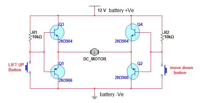
1) Connect collector* of both NPN transistors and connect it with +Ve terminal (RED) of battery
2) Connect collectors of both PNP transistors and connect them with –Ve terminal (BLACK) of battery
3) Connect emitter* of PNP and NPN transistors and connect them with motor terminals as shown
4) Connect base* of NPN and PNP transistors on one side as shown
5) Connect one 10 K resistor from collector to base and one push button between base and collector as shown on both side
*note: for collector, emitter and base terminals of transistor please refer the datasheet of 2N3904/2N3906
• Now when button 1 is pressed the transistor Q1 and Q4 are switched ON, so motor will start rotating clockwise
• When button 2 is pressed the transistor Q2 and Q3 are switched ON, so motor will start rotating anticlockwise
That’s it. Out task is complete. As you press button 1, the motor will rotate clockwise, the string gets wrapped and basket lifts up. Similarly, as you press button 2, the motor will rotate anticlockwise, the string unwrapped and basket moves down.
Here is the snap of project arrangement.

Fig. 8: Prototype of Electronically controlled Simple Dc Motor based Crane
Here I have used 100 RPM motor. With this, I can lift 200 gm weight. As I said earlier, to lift up more weight, use lower RPM motor like 30 RPM, 10 RPM, and 5 RPM etc.
Circuit Diagrams
Project Video
Filed Under: Electronic Projects
Filed Under: Electronic Projects

Questions related to this article?
👉Ask and discuss on Electro-Tech-Online.com and EDAboard.com forums.
Tell Us What You Think!!
You must be logged in to post a comment.