Engineers Garage

  • Electronic Projects & Tutorials
    • Electronic Projects
      • Arduino Projects
      • AVR
      • Raspberry pi
      • ESP8266
      • BeagleBone
      • 8051 Microcontroller
      • ARM
      • PIC Microcontroller
      • STM32
    • Tutorials
      • Audio Electronics
      • Battery Management
      • Brainwave
      • Electric Vehicles
      • EMI/EMC/RFI
      • Hardware Filters
      • IoT tutorials
      • Power Tutorials
      • Python
      • Sensors
      • USB
      • VHDL
    • Circuit Design
    • Project Videos
    • Components
  • Articles
    • Tech Articles
    • Insight
    • Invention Stories
    • How to
    • What Is
  • News
    • Electronic Product News
    • Business News
    • Company/Start-up News
    • DIY Reviews
    • Guest Post
  • Forums
    • EDABoard.com
    • Electro-Tech-Online
    • EG Forum Archive
  • DigiKey Store
    • Cables, Wires
    • Connectors, Interconnect
    • Discrete
    • Electromechanical
    • Embedded Computers
    • Enclosures, Hardware, Office
    • Integrated Circuits (ICs)
    • Isolators
    • LED/Optoelectronics
    • Passive
    • Power, Circuit Protection
    • Programmers
    • RF, Wireless
    • Semiconductors
    • Sensors, Transducers
    • Test Products
    • Tools
  • Learn
    • eBooks/Tech Tips
    • Design Guides
    • Learning Center
    • Tech Toolboxes
    • Webinars & Digital Events
  • Resources
    • Digital Issues
    • EE Training Days
    • LEAP Awards
    • Podcasts
    • Webinars / Digital Events
    • White Papers
    • Engineering Diversity & Inclusion
    • DesignFast
  • Guest Post Guidelines
  • Advertise
  • Subscribe

DIY IR Remote Receiver for Canon Cameras

By Ganesh Selvaraj February 1, 2015

This tutorial shows you how to make an IR receiver for Canon camera with minimum parts. The receiver will let us control the shutter button of any canon camera with any IR remote control.

Required components

1. TSOP 1738 Receiver
 
2. 330 ohms resistor + LED
 
3. Electrolytic Capacitor –100uF/16V
 
4. PnP Transistor – BC558
 
5. Female Header
 
6. Female USB connector
 
7. Switch
 
8. 7805 Regulator IC
 
9. 9V battery
 
10.Battery clip
 
11.Small PCB
 
12.A canon camera


Installing CHDK

Well before we proceed  with making the receiver, we need to first install the Canon Hack Development Kit into the camera. There are many methods to install this in your camera that can be availed from various online tutorials. For convenience, let me just explain you briefly how to do it.

1.Download the program called Automatic Camera Identifier and Downloader aka ACID utility program from here: http://chdk.wikia.com/wiki/ACID

2.Take a picture using your camera; remove the memory card and insert it into your computer (using a card reader).
 
3.Now run the ACID utility program and drag & drop the photo you just captured.
 
The program would now tell you the version of your camera’s firmware and model number. It can also download the appropriate CHDK file if you choose to do so.
 
4.Once you have downloaded the CHDK zip file, extract it and paste the files in the root directory of your memory card.
 
5.Now insert the card back into your camera.
 
6.Do not switch on the camera using the power button. Instead use the play button and turn on the camera.
 
7.Then click on menu and scroll down until you see something called ‘Firmware Update’

Screenshot of settings on a Canon Camera for Firmware Update

Fig. 1: Screenshot of settings on a Canon Camera for Firmware Update

 
8.Click on it and then press ok. That’s it! You have CHDK installed in your camera now.
 
Don’t worry; your camera’s firmware is not really being modified here. Whenever you turn on the camera using normal power button, it loads the original settings only. Whenever you want CHDK to be booted, you have to follow step 6-8
 
 
Enabling USB Remote
 
1. Load the camera in CHDK mode and go to CHDK settings.
 
2. Set Enable Remote, Switch Type to ‘One Push’ and control mode to   ‘normal’
 

Screenshot of settings on a Canon Camera for enabling USB Camera

Fig. 2: Screenshot of settings on a Canon Camera for enabling USB Camera

 
Well we have finished the software part so let’s move on to the hardware part.

Hardware Setup

First, test the circuit on a breadboard and then proceed to soldering. You don’t need to connect the USB part while testing. Just check if the LED glows for a second after pressing any button on the remote.

Once you have verified the circuit on breadboard, proceed to soldering.

Gather all the parts shown in the image.

Image showing components required for making IR Remote Receiver for Canon Cameras

Fig. 3: Image showing components required for making IR Remote Receiver for Canon Cameras

Start by setting up the USB connector onto the PCB. You may have to enlarge the holes to make it fit properly.
 

Image showing components required for making IR Remote Receiver for Canon Cameras

Fig. 4: Image showing widen PCB holes to fit USB Connector

After fixing the connector, bend its leads to lock it onto the PCB. This would make it stay firm when connecting or removing the cable from it.

Image showing USB connector mounted on PCB

Fig. 5: Image showing USB connector mounted on PCB

Next, solder the +5V and GND pins of the USB connector. Add a diode to the +5V line. This would prevent the camera’s port from being damaged in case anything goes wrong and the polarity gets reversed.

Image showing USB connector soldered to PCB

Fig. 6: Image showing USB connector soldered to PCB

Add the components one by one starting from the transistor. Solder transistor’s collector lead to the Diode and the 330 ohms resistor.

Image showing transistor circuit soldered near USB connector

Fig. 7: Image showing transistor circuit soldered near USB connector

Next, add the 100uF capacitor, connecting the positive end to the base of the transistor. Instead of soldering the TSOP receiver directly to the PCB, I have soldered a female header since TSOP  can be easily damaged by the solder’s heat.

Image showing female header soldered on PCB to fit TSOP receiver

Fig. 8: Image showing female header soldered on PCB to fit TSOP receiver

Make sure you place the components in such a way that all the leads connecting to ground are on one side and the leads connecting to VCC are on other side. This minimizes polarity errors and also makes it organized.

Image showing ground and VCC connections soldered to opposite sides to minimize polarity error

Fig. 9: Image showing ground and VCC connections soldered to opposite sides to minimize polarity error

You can even add a resistor and an LED directly to the 5V output as a power indicator  along with a switch.

Image showing power indicator circuit soldered on PCB for IR Receiver

Fig. 10: Image showing power indicator circuit soldered on PCB for IR Receiver

After all these components are added, add the voltage regulator and the battery clip at the end.

Image showing voltage regulator soldered on PCB for IR receiver

Fig. 11: Image showing voltage regulator soldered on PCB for IR receiver

Now connect a 9V battery to the clip and switch on the circuit.  Don’t forget to plug in the TSOP receiver to the female header.
 
You should see the power indicator LED glowing constantly. The LED connected parallel to the USB port glows as soon as you switch ON and then slowly fades away.
 
Now take any IR remote, point towards the TSOP and press any key. If the LED glows and fades away after a while, it means your circuit is perfect.
 

Here is the Testing video: http:http://youtu.be/Bdcy53L41dE
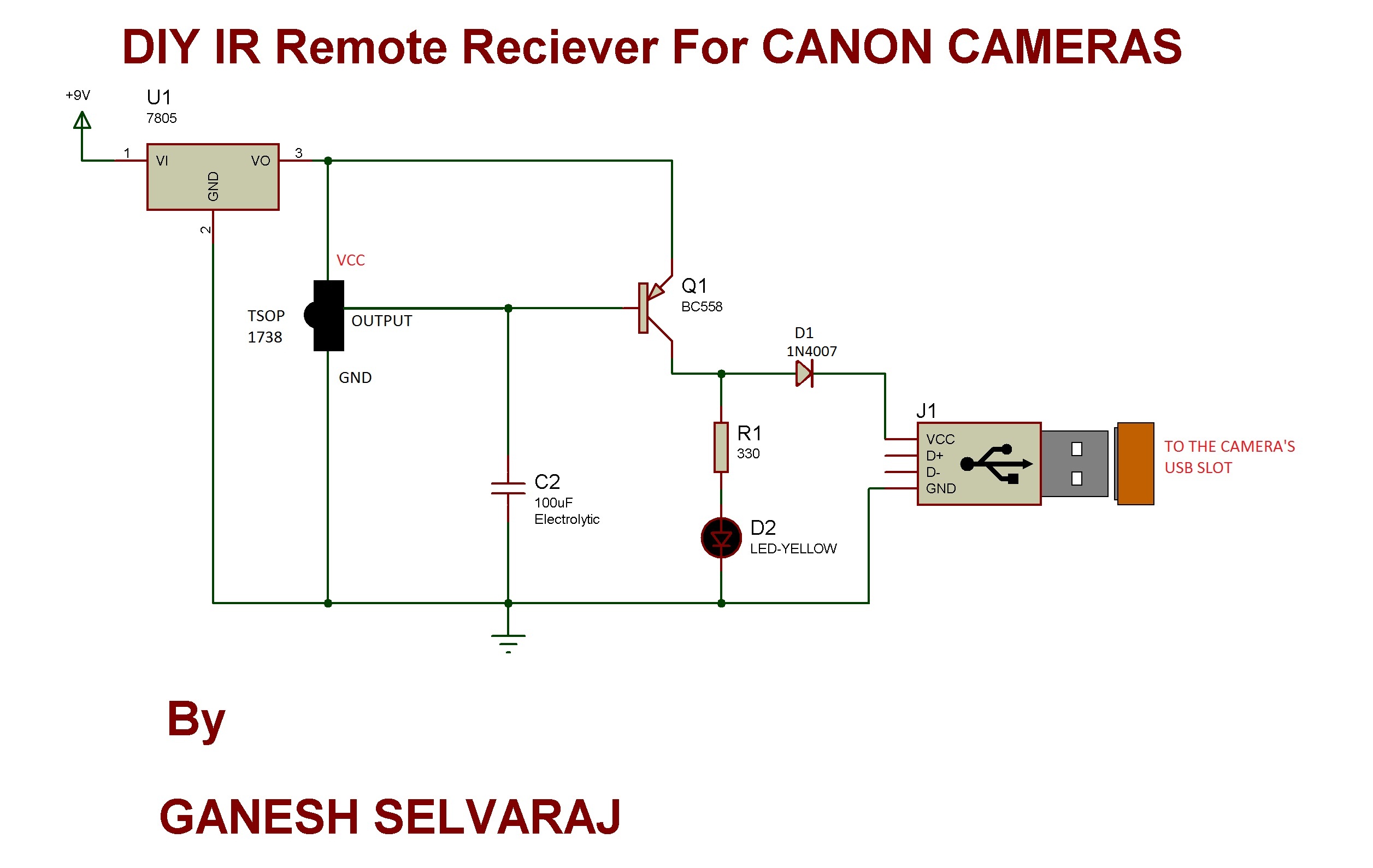
Once you are done with the testing, connect the USB cable to the circuit and the camera. Connect the battery and switch on the circuit. Turn on the camera in CHDK mode.
 
Now point  the IR remote (TV’s/VCR’s) and press any button on it. You should see the LED connected parallel to the USB connector glowing and pictures being clicked in the camera.


Circuit Diagrams

Circuit-Diagram-TSOP-1738-Based-USB-IR-Remote-Receiver

Project Video


Filed Under: Electronic Projects


Next Article

← Previous Article
Next Article →

Questions related to this article?
👉Ask and discuss on Electro-Tech-Online.com and EDAboard.com forums.


Tell Us What You Think!! Cancel reply

You must be logged in to post a comment.

EE TECH TOOLBOX

“ee
Tech Toolbox: 5G Technology
This Tech Toolbox covers the basics of 5G technology plus a story about how engineers designed and built a prototype DSL router mostly from old cellphone parts. Download this first 5G/wired/wireless communications Tech Toolbox to learn more!

EE Learning Center

EE Learning Center
“engineers
EXPAND YOUR KNOWLEDGE AND STAY CONNECTED
Get the latest info on technologies, tools and strategies for EE professionals.

HAVE A QUESTION?

Have a technical question about an article or other engineering questions? Check out our engineering forums EDABoard.com and Electro-Tech-Online.com where you can get those questions asked and answered by your peers!


RSS EDABOARD.com Discussions

  • Identification of a 6 pin smd chip (sto-23-6) marked E2
  • Dynacord enter protect
  • IGBTs without negative gate drive
  • Need suggestions in task NI6363 retrigger (analog trigger)
  • Monte-Carlo simulation error on ADE-XL

RSS Electro-Tech-Online.com Discussions

  • Faulty heat air gun (dc motor) - problem to locate fault due to Intermittent fault
  • Fun with AI and swordfish basic
  • Does US electric code allow branching ?
  • Sump pit water alarm - Kicad 9
  • turbo jet fan - feedback appreciated.

Featured – LoRa/LoRaWan Series

  • What is the LoRaWAN network and how does it work?
  • Understanding LoRa architecture: nodes, gateways, and servers
  • Revolutionizing RF: LoRa applications and advantages
  • How to build a LoRa gateway using Raspberry Pi
  • How LoRa enables long-range communication
  • How communication works between two LoRa end-node devices

Recent Articles

  • How IoT network topologies work
  • The top five AI startups to watch in 2025
  • STMicroelectronics unveils SoC based on secure MCU
  • Nexperia’s 48 V ESD diodes support higher data rates with ultra-low capacitance design
  • Taoglas releases Patriot antenna with 18 integrated elements covering 600 to 6000 MHz

EE ENGINEERING TRAINING DAYS

engineering

Submit a Guest Post

submit a guest post
Engineers Garage
  • Analog IC TIps
  • Connector Tips
  • Battery Power Tips
  • DesignFast
  • EDABoard Forums
  • EE World Online
  • Electro-Tech-Online Forums
  • EV Engineering
  • Microcontroller Tips
  • Power Electronic Tips
  • Sensor Tips
  • Test and Measurement Tips
  • 5G Technology World
  • Subscribe to our newsletter
  • About Us
  • Contact Us
  • Advertise

Copyright © 2025 WTWH Media LLC. All Rights Reserved. The material on this site may not be reproduced, distributed, transmitted, cached or otherwise used, except with the prior written permission of WTWH Media
Privacy Policy

Search Engineers Garage

  • Electronic Projects & Tutorials
    • Electronic Projects
      • Arduino Projects
      • AVR
      • Raspberry pi
      • ESP8266
      • BeagleBone
      • 8051 Microcontroller
      • ARM
      • PIC Microcontroller
      • STM32
    • Tutorials
      • Audio Electronics
      • Battery Management
      • Brainwave
      • Electric Vehicles
      • EMI/EMC/RFI
      • Hardware Filters
      • IoT tutorials
      • Power Tutorials
      • Python
      • Sensors
      • USB
      • VHDL
    • Circuit Design
    • Project Videos
    • Components
  • Articles
    • Tech Articles
    • Insight
    • Invention Stories
    • How to
    • What Is
  • News
    • Electronic Product News
    • Business News
    • Company/Start-up News
    • DIY Reviews
    • Guest Post
  • Forums
    • EDABoard.com
    • Electro-Tech-Online
    • EG Forum Archive
  • DigiKey Store
    • Cables, Wires
    • Connectors, Interconnect
    • Discrete
    • Electromechanical
    • Embedded Computers
    • Enclosures, Hardware, Office
    • Integrated Circuits (ICs)
    • Isolators
    • LED/Optoelectronics
    • Passive
    • Power, Circuit Protection
    • Programmers
    • RF, Wireless
    • Semiconductors
    • Sensors, Transducers
    • Test Products
    • Tools
  • Learn
    • eBooks/Tech Tips
    • Design Guides
    • Learning Center
    • Tech Toolboxes
    • Webinars & Digital Events
  • Resources
    • Digital Issues
    • EE Training Days
    • LEAP Awards
    • Podcasts
    • Webinars / Digital Events
    • White Papers
    • Engineering Diversity & Inclusion
    • DesignFast
  • Guest Post Guidelines
  • Advertise
  • Subscribe