The circuit presented here transmits pulses wirelessly to long distance (more than 20 meter) using keychain LASER (readily available in market). A transmitter generates continuous pulses that are fed to LASER. LASER blinks at the rate of pulse frequency and emits light pulses. LDR on the receiver side, detects this light pulses and reproduces it at the output. So the same pulses that are generated at transmitter side can be received at receiver side to longer distance.
To begin with the first thing that is required for this project is to prepare LASER. So let us start with how to prepare a LASER.
LASER key-chains available in the market are like this
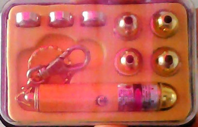
Fig. 2: Image of LASER keychains
To prepare it for the project we need to take out its anode and cathode terminals to provide pulses. In order to remove button cells and keychain part from backside of the keychain. You will see one small spring, which is cathode terminal. Connect one wire with this as shown in the figure below.

Fig. 3: Iamge Of Cathode Terminal And Connected Wires
Remove the cap from the front side of the laser keychain. The anode terminal is exactly below the cap – circular ring type. Take one single core copper wire and wind it in circles (ring type) around the terminal as shown in figure

Fig. 4: Image Of LASER keychain
Finally fix the push button switch with tape and also fix the LASER on any base like match-box or small plastic box as shown in the figure below
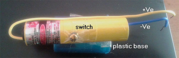
Now this LASER keychain is ready for use, in this project. It will work similar to any LED. A pulse can be given to +Ve terminal and –Ve terminal can be connected to ground.
Transmitter
It is made up using IC555. IC555 is connected in astable configuration. It generates continuous pulses. The frequency is determined by values of RC components R1, R2, pot R3 and C1. Frequency can be varied from 1 Hz to 10 Hz by varying pot R3 (note – for visual effect (demonstration) the pulse frequency is kept low. The frequency can be kept high in terms of KHz also). These pulses are fed to LASER through current limiting resistor. So LASER will blink at applied frequency.
Receiver
The receiver is also made up of IC555. But here the receiver is connected in monostable configuration. The output pulse time period is determined by RC components R5 and C3. The time period is kept very low (0.11 ms) as compared to transmitted pulse time period (0.1 to 1 sec). The LDR is connected to trigger input pin (no. 2) in such a way that it generates trigger pulse when LASER light falls on it.
Circuit Operation
· At first the supply is given to the receiver, because LASER light is falling on LDR, the receiver output is low and receiver LED is off.
· In the next stage when supply is given to the transmitter, the LASER starts blinking
· LASER and LDR are perfectly aligned
· So LDR receives LASER light and generates trigger pulse to IC555
· IC555 gives high output till the duration of the LASER light pulse
· So receiver LED blinks at the same rate of transmitter frequency
· This receiver LED blinking rate can be changed by varying pot R3 at transmitter side
Circuit Diagrams
Project Components
Project Video
Filed Under: 555 Timers, Electronic Projects
Filed Under: 555 Timers, Electronic Projects

Questions related to this article?
👉Ask and discuss on Electro-Tech-Online.com and EDAboard.com forums.
Tell Us What You Think!!
You must be logged in to post a comment.