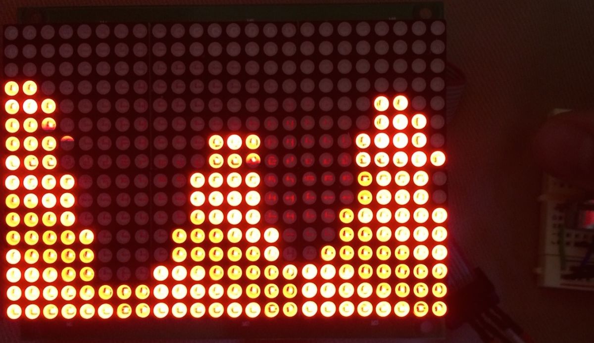
In one of the projects of Workshop Weekend, that comprises complex programming and nominal soldering skill and is known as LED Matrix Graph, detects two physical values over time. It is a simple program that requires two potentiometers in the beginning but then the variation replaces the potentiometers with Light-dependent Resistors (LDRs), then with capacitive sensors. Further, the representation of two values is graphically based on a 16×24 Red LED Matrix, like this one from Adafruit.

To complete the project, components required are 18×24 LED Matrix, 2 Linear Potentiometers, 2 Light-dependent Resistors, 2× 10 kΩ resistors, 2 paperclips, 2× 1 MΩ resistors, 10 wires, Solderless breadboard. The LED Matrix board is prepared accordingly, as it might include soldering iron to bridge jumper J5 on the back of the board.
For the wiring section, the circuit is build and jumper wires are plugged into the ribbon cable and Arduino as shown in this Adafruit tutorial. But the 5V (red) and GND (black) wires are plugged into the breadboard and not directly into the Arduino. For less debugging, try to match the colors if possible.
The software for the LED matrix board can be obtained from the HT1632 library, which can be easily downloaded and installed. The codes provided by the team is available on the website.They are copied into a new Arduino sketch and the project is uploaded.
Filed Under: Reviews


Questions related to this article?
👉Ask and discuss on EDAboard.com and Electro-Tech-Online.com forums.
Tell Us What You Think!!
You must be logged in to post a comment.