Ever wanted to make your own table lamp? If yes then you have come to the right tutorial! This project shows you how to make table lamp using a bunch of LEDs and 555 Timer circuit.

Fig. 1: Prototype of 555 IC based Table Lamp Controller
DIY Table Lamp: Final Set up
Components Required
Designing
Our first problem is that we can’t give 12V directly to an LED which would simply burn it. Well you may say that adding a series resistor would solve that problem but let’s see what happens when we do that.

Fig. 2: Circuit Diagram of LED Driver

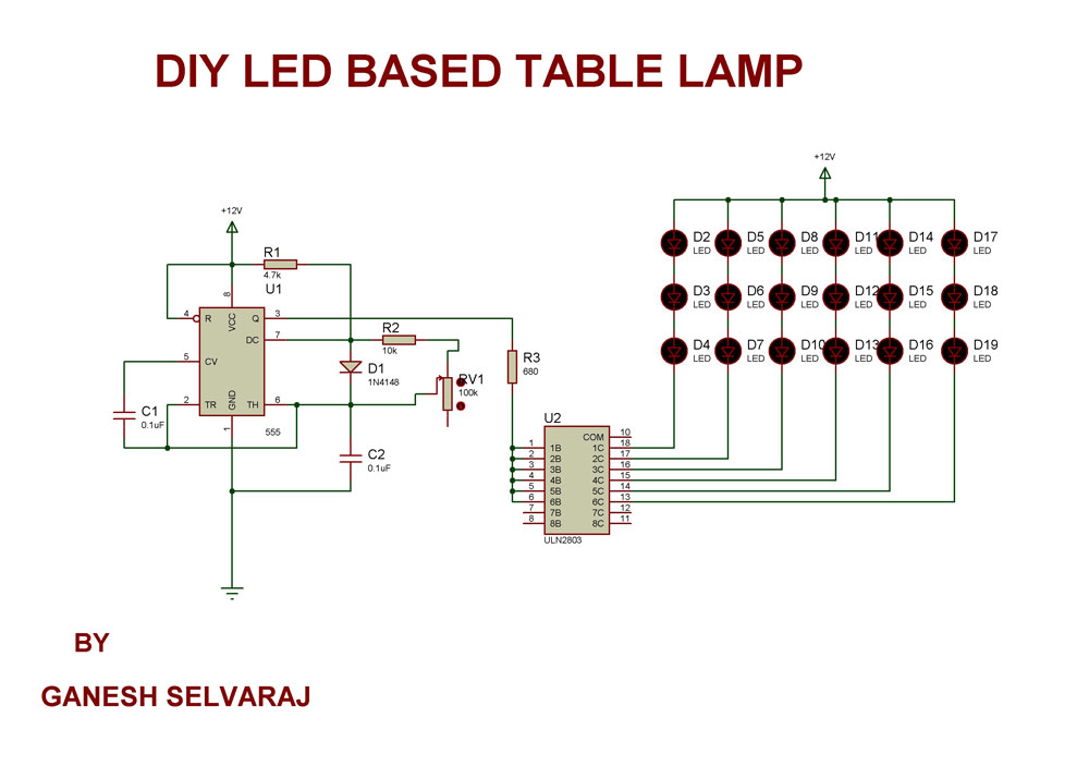
Fig. 3: Circuit Diagram of Multiple LEDs Driver
Eliminating the Resistors
Soldering
Part 1: LEDs

Fig. 4: Image showing LEDs and PCB
Take a small PCB and 18 white LEDs

Fig. 5: Image showing LEDs arranged in matrix on PCB

Fig. 6: Image showing LED terminals popping out on backside of PCB
Now remove all the LEDs and start soldering column by column i.e., three at a time.

Fig. 7: Image showing soldered LED terminals on PCB

Fig. 8: Image showing polarity of LEDs soldered on PCB

Fig. 9: Image showing soldering for positive terminals of LEDs on PCB

Fig. 10: Image showing soldered positive terminals of LEDs on PCB
Top view of the PCB

Fig. 11: Image showing LED matrix on PCB
Remember: While soldering at each step, check if the joints are done correctly and if the LED is working using a multimeter’s continuity feature. This way you can correct the errors in the circuit easily and also replace the LEDs if any of them are damaged.
Making the Circuit
Part 2: Circuit
Take another small PCB. Since soldering ICs directly onto PCB is risky, I’m using an 8 pin base and an 18 pin base for 555 Timer and ULN2803 ICs. Position the bases to see if there is enough space for other components.

Fig. 12: Image showing IC holders placed on PCB
Once you are satisfied, start soldering the bases onto the PCB.

Fig. 13: Image showing soldering done on IC holders on PCB

Fig. 14: Image showing soldered IC holders on PCB
Note: Don’t add the potentiometer right now.

Fig. 15: Image showing positive and negative wire connections taken out from LED Matrix

Fig. 16: Image showing wire connections between LED matrix and control circuit

Fig. 17: Image showing circuit connections between LED matrix and control circuit
Now solder two wires for the power supply and also a wire connecting the +ve terminal of the top LEDs to the +ve line on the circuit board.

Fig. 18: Image showing power supply connections for PCBs
Fig. 19: Image showing complete circuit of 555 IC based automatic table lamp

Fig. 20: Image of LEDs glowing in LED Matrix

Fig. 21: Image showing completed PCB circuits for LED Matrix and 555 IC based circuit

Fig. 22: Image showing complete circuit assembled in a box

Fig. 23: Image showing placement of pot on box to control brightness of table lamp

Fig. 24: Image showing 555 IC based Table Lamp Controller
Circuit Diagrams
Filed Under: Electronic Projects

Questions related to this article?
👉Ask and discuss on Electro-Tech-Online.com and EDAboard.com forums.
Tell Us What You Think!!
You must be logged in to post a comment.