This project is based on Arduino Platform. In Electronics, there are many display devices available in or market like Liquid Crystal Display, Seven Segment Display, Dot Matrix LED display, Graphic Display etc. and they are used to display some information in many places like railway station, bus stand, mall, multiplex, hospital, school, colleges and many other places. For this project reader should have knowledge of how to start with arduino.

Fig. 1: Prototype of Arduino controlled Dot Matrix Display

Fig. 2: Image of Dot Matrix Display showing Text Message

Fig. 3: Image of Dot Matrix Display showing Text Animation

Fig. 4: Pin Diagram and Image of Dot Matrix Display
AED dot matrix display consists of a matrix of LED’s arranged in a rectangular configuration. The desired character or graphics can be displayed by switching ON /OFF a desired configuration of LED’s. Common display configurations available are 7×5, 8×8, 7×15, etc. LED dot matrix can be used in simple display applications where the resolution is not a big concern. The figure below shows the arrangement of LEDs in a typical 7×5 dot matrix display.Any individual LED or a group of LEDs in the matrix can be activated by switching the required number of rows and columns.n L

Fig. 5:
Screenshot of Serial Port used to send Text Message to Arduino controlled LED Display

Fig. 6: Image of LED Display Board flashing received message

Fig. 7: Representational Image of Dot Matrix Display
Block Diagram
Light-emitting diodes (LEDs) provide a cheap and convenient way to display information electronically. LEDs are tiny light sources that are illuminated solely by the movement of electrons in semiconducting materials. They emit light when forward-biased, fit easily into an electrical circuit, and are durable. LEDs are often arranged in patterns to display information. The seven-segment configuration of an LED arranged in the form of the digit 8 can be restrictive in that it does not adequately allow the display of some alphanumeric characters. By contrast, the versatility of a dot-matrix arrangement allows an LED unit to display complicated shapes.
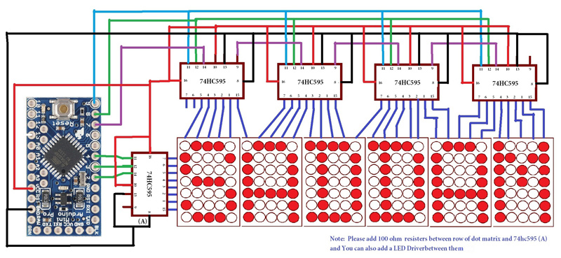
In this circuit I have used six 5×7 dot matrix displays to display any message. and in the circuit I have used 5 shift register(74595) which controlled by Arduino to display Desire result or information on Dot matrix display and here one led driver(2803) also used for maintaining the brightness of the dot matrix display. Here five shift register used in which four shift registers are used for rotating or changing the column and one is used for changing row data to display desire information on dot matrix display.

Fig. 8: Block Diagram of Arduino based Led Display Panel
In this project serial communication is also used for sending desire data or information serially for displaying on dot matrix display.
Only six pins are used for controlling and sending data to display. Arduino Pin 3 and 4 are connected to the sh_cp(11) and st_cp(12) of shift register (Row) respectively for controlling the Row data. And pin 4 is used for sending data to shift resister’s (Row) ds pin. This data is sends serially from microcontroller to shift register.. And pin 8, 9 are connected tosh_cp(11) and st_cp(12) of shift register (Column) respectively for controlling the column data. And pin 7 is used for sending data to shift register’s ds pin (column) for changing the column.
In programming a two dimensional array has defined, which includes almost all integer, character, operator and symbols.

Fig. 9: Screenshot of Arduino Code used to store characters in an array
Components Used
Shift Register
The 74HC595; 74HCT595 are high-speed Si-gate CMOS devices and are pin compatiblewith Low-power Schottky TTL (LSTTL).

Fig. 10: Pin Diagram of 74HC595 Shift Register IC
The 74HC595; 74HCT595 are 8-stage serial shift registers with a storage register and3-state outputs. The registers have separate clocks. Data is shifted on the positive-going transitions of the shift register clock input (SHCP).The data in each register is transferred to the storage register on a positive-going transition of the storage register clock input (STCP). If both clocks are connected together, the shift register will always be one clock pulse ahead of the storage register. The shift register has a serial input (DS) and a serial standard output (Q7S) for cascading. It is also provided with asynchronous reset (active LOW) for all 8 shift register stages. The storage register has 8 parallel 3-state bus driver outputs. Data in the storage register appears at the output whenever the output enable input (OE) is LOW.

Fig. 11: Image of 74HC595 Shift Register IC
LED driver
Bring in some muscle to your output pins with 8 mighty Darlington. This DIP chip contains 8 drivers that can sink 500mA from a 50V supply and has kickback diodes included inside for driving coils. This will let your little microcontroller or microcomputer power solenoids, DC motors (in one direction) and unipolar stepper motors. Please note, this is an ‘open collector’ driver – it can only be used to connect the load to ground and there will be a 1 Volt (or more) ‘drop’ across the internal transistors. The inputs can be driven by 3.3V or 5V logic. Fits nicely in any breadboard or perfboard.

Fig. 12: Pin Diagram and Image of ULN2803 LED Driver IC
Arduino Pro Mini
Arduino Pro Mini is a 3.3V Arduino running the 8MHz boot-loader. Arduino Pro Mini does not come with connectors populated so that you can solder in any connector or wire with any orientation you need. We recommend first time Arduino users start with the Uno R3. It’s a great board that will get you up and running quickly. The Arduino Pro series is meant for users that understand the limitations of system voltage (3.3V), lack of connectors, and USB off board.

Fig. 13: Typical Image of Arduino Pro Mini
FTDI Basic
This is a basic breakout board for the FTDI FT232RL USB to serial IC , based on the well famous FTDI-Basic board from Spark-fun. The pin out of this board matches the FTDI cable to work with official Arduino and cloned Arduino boards. The board can be used to download the sketches to Arduino Boards without on board USB interface and can also be used for general USB to serial converter applications.

Fig. 14: Typical Image of FTDI USB to Serial Converter
Project Source Code
### #define shcp_colun 7 // coln #define stcp_colun 8 // coln #define ds_colun 9 // coln #define shcp_row 10 // row #define stcp_row 11 //row #define ds_row 13 int scr_speed,p,j,i,lenth,temp; int data_row,data_colon; int move_data[30]; int colun_data[31]={1,0,0,0,0,0,0,0,0,0,0,0,0,0,0,0,0,0,0,0,0,0,0,0,0,0,0,0,0,0,0}; char inputString[100]; char font_5x7[95][6] = { {0x00,0x00,0x00,0x00,0x00}, // {0x00,0x00,0x7d,0x00,0x00}, // ! {0x00,0x70,0x00,0x70,0x00}, // " {0x14,0x7f,0x14,0x7f,0x14}, // # {0x12,0x2a,0x6b,0x2a,0x24}, // $ {0x32,0x34,0x08,0x16,0x26}, // % {0x36,0x49,0x4d,0x52,0x25}, // & {0x00,0x00,0x70,0x00,0x00}, // ' {0x00,0x3e,0x41,0x00,0x00}, // ( {0x00,0x0,0x41,0x3e,0x00}, // ) {0x2a,0x1c,0x08,0x1c,0x2a}, // * {0x08,0x08,0x3e,0x08,0x08}, // + {0x00,0x01,0x06,0x04,0x00}, // , {0x08,0x08,0x08,0x08,0x00}, // - {0x00,0x00,0x03,0x03,0x00}, // . {0x02,0x04,0x08,0x10,0x20}, // / {0x3e,0x41,0x41,0x3e,0x00}, // 0 {0x11,0x21,0x7f,0x01,0x01}, // 1 {0x21,0x43,0x45,0x49,0x31}, // 2 {0x22,0x49,0x49,0x49,0x36}, // 3 {0x0c,0x14,0x24,0x7f,0x04}, // 4 {0x72,0x51,0x51,0x51,0x4e}, // 5 {0x3e,0x49,0x49,0x49,0x26}, // 6 {0x60,0x40,0x43,0x4c,0x70}, // 7 {0x36,0x49,0x49,0x49,0x36}, // 8 {0x32,0x49,0x49,0x49,0x3e}, // 9 {0x00,0x36,0x36,0x00,0x00}, // : {0x01,0x36,0x34,0x00,0x00}, // ; {0x08,0x14,0x22,0x41,0x00}, // < {0x14,0x14,0x14,0x14,0x00}, // = {0x00,0x41,0x22,0x14,0x08}, // > {0x30,0x40,0x45,0x48,0x30}, // ? {0x3e,0x41,0x59,0x55,0x3c}, // @ {0x3f,0X44,0x44,0x44,0x3f}, // A {0x7f,0x49,0x49,0x49,0x36}, // B {0x3e,0x41,0x41,0x41,0x22}, // C {0x41,0x7f,0x41,0x41,0x3e}, // D {0x7f,0x49,0x49,0x49,0x41}, // E {0x7f,0x48,0x48,0x48,0x40}, // F {0x3e,0x41,0x45,0x45,0x26}, // G {0x7f,0x08,0x08,0x08,0x7f}, // H {0x41,0x41,0x7f,0x41,0x41}, // I {0x42,0x41,0x41,0x7e,0x40}, // J {0x7f,0x08,0x14,0x22,0x41}, // K {0x7f,0x01,0x01,0x01,0x01}, // L {0x7f,0x20,0x18,0x20,0x7f}, // M {0x7f,0x20,0x18,0x06,0x7f}, // N {0x3e,0x41,0x41,0x41,0x3e}, // O {0x7f,0x48,0x48,0x48,0x30}, // P {0x3c,0x42,0x46,0x42,0x3d}, // Q {0x7f,0x48,0x4c,0x4a,0x31}, // R {0x32,0x49,0x49,0x49,0x26}, // S {0x40,0x40,0x7f,0x40,0x40}, // T {0x7e,0x01,0x01,0x01,0x7e}, // U {0x7c,0x02,0x01,0x02,0x7c}, // V {0x7e,0x01,0x06,0x01,0x7e}, // W {0x41,0x22,0x1c,0x22,0x41}, // X {0x70,0x08,0x0F,0x08,0x70}, // Y {0x43,0x45,0x49,0x51,0x61}, // Z {0x00,0x7f,0x41,0x00,0x00}, // [ {0x20,0x10,0x08,0x04,0x02}, // "" {0x00,0x00,0x41,0x7f,0x00}, // ] {0x00,0x20,0x40,0x20,0x00}, // ^ {0x01,0x01,0x01,0x01,0x01}, // _ {0x00,0x40,0x20,0x00,0x00}, // ` {0x0c,0x12,0x14,0x0e,0x01}, // a {0x7e,0x11,0x11,0x0e,0x00}, // b {0x0e,0x11,0x11,0x11,0x00}, // c {0x0e,0x11,0x11,0x7e,0x00}, // d {0x0e,0x15,0x15,0x0d,0x00}, // e {0x08,0x3f,0x48,0x20,0x00}, // f {0x12,0x29,0x29,0x1e,0x00}, // g {0x7f,0x08,0x08,0x07,0x00}, // h {0x00,0x11,0x5f,0x01,0x00}, // i {0x00,0x12,0x11,0x5e,0x00}, // j {0x7f,0x04,0x0a,0x11,0x00}, // s {0x00,0x41,0x7f,0x01,0x00}, // l {0x3f,0x10,0x0f,0x10,0x0f}, // m {0x20,0x1f,0x10,0x10,0x0f}, // n {0x0e,0x11,0x11,0x0e,0x00}, // o {0x1f,0x14,0x14,0x08,0x00}, // p {0x08,0x14,0x14,0x1f,0x02}, // q {0x1f,0x08,0x10,0x00,0x00}, // r {0x09,0x15,0x15,0x12,0x00}, // s {0x10,0x7e,0x11,0x02,0x00}, // t {0x1e,0x01,0x01,0x1e,0x01}, // u {0x1e,0x01,0x1e,0x00,0x00}, // v {0x1e,0x01,0x06,0x01,0x1e},// w {0x11,0x0a,0x04,0x0a,0x11}, // x {0x19,0x05,0x06,0x18,0x00}, // y {0x13,0x15,0x19,0x11,0x00}, // z {0x00,0x08,0x36,0x41,0x00}, // { {0x00,0x00,0x7f,0x00,0x00}, // | {0x00,0x41,0x36,0x08,0x00}, // } {0x08,0x10,0x08,0x10,0x00}, // ~ }; void setup() { Serial.begin(9600); pinMode(shcp_colun, OUTPUT); pinMode(stcp_colun, OUTPUT); pinMode(ds_colun, OUTPUT); pinMode(shcp_row, OUTPUT); pinMode(stcp_row, OUTPUT); pinMode(ds_row, OUTPUT); } void loop() { int i; while(1){ char *Str="Dot Matrix by SADDAM KHAN "; while(*Str!='�'){ printf(*Str); Str++; } } } void scroll(char a,char b,char c,char d,char e) //input_string function // { int count=6; while(count>0){ move_data[0]=a;a=b;b=c;c=d;d=e;e=0; for(scr_speed=0;scr_speed<50;scr_speed++){ for(i=0;i<30;i++){ temp=move_data[i]; for(j=0;j<8;j++){ data_row=(temp&(0x80)); digitalWrite(ds_row,data_row); temp<<=1; digitalWrite(shcp_row,HIGH); for(int z=0;z<3;z++){} digitalWrite(shcp_row,LOW); } data_colon=colun_data[i]; digitalWrite(ds_colun, data_colon); digitalWrite(shcp_colun,HIGH);//delay(1); digitalWrite(shcp_colun,LOW); digitalWrite(stcp_row,HIGH);//delay(1); digitalWrite(stcp_colun,HIGH); digitalWrite(stcp_row,LOW); digitalWrite(stcp_colun,LOW); if(Serial.available()){serial_string();} } } for(i=29;i>0;i--){move_data[i]=move_data[i-1];} count--; } } void printf(char khan) { p=khan-32; scroll(font_5x7[p][0],font_5x7[p][1],font_5x7[p][2],font_5x7[p][3],font_5x7[p][4]); } void serial_string() { for(i=0;i<100;i++){ inputString[i]=0;} lenth=0; for(lenth=0;lenth<3;lenth++){ inputString[lenth]=' ';} lenth=3; while(1){ while(Serial.available()){ char inChar = (char)Serial.read(); inputString[lenth]= inChar; lenth++; if(inChar=='n'){ while(1){ for(int z=0;z<lenth-2;z++){ printf(inputString[z]);} }}}} } ###
Circuit Diagrams
Project Video
Filed Under: Electronic Projects
Filed Under: Electronic Projects

Questions related to this article?
👉Ask and discuss on Electro-Tech-Online.com and EDAboard.com forums.
Tell Us What You Think!!
You must be logged in to post a comment.