Engineers Garage

  • Electronic Projects & Tutorials
    • Electronic Projects
      • Arduino Projects
      • AVR
      • Raspberry pi
      • ESP8266
      • BeagleBone
      • 8051 Microcontroller
      • ARM
      • PIC Microcontroller
      • STM32
    • Tutorials
      • Audio Electronics
      • Battery Management
      • Brainwave
      • Electric Vehicles
      • EMI/EMC/RFI
      • Hardware Filters
      • IoT tutorials
      • Power Tutorials
      • Python
      • Sensors
      • USB
      • VHDL
    • Circuit Design
    • Project Videos
    • Components
  • Articles
    • Tech Articles
    • Insight
    • Invention Stories
    • How to
    • What Is
  • News
    • Electronic Product News
    • Business News
    • Company/Start-up News
    • DIY Reviews
    • Guest Post
  • Forums
    • EDABoard.com
    • Electro-Tech-Online
    • EG Forum Archive
  • DigiKey Store
    • Cables, Wires
    • Connectors, Interconnect
    • Discrete
    • Electromechanical
    • Embedded Computers
    • Enclosures, Hardware, Office
    • Integrated Circuits (ICs)
    • Isolators
    • LED/Optoelectronics
    • Passive
    • Power, Circuit Protection
    • Programmers
    • RF, Wireless
    • Semiconductors
    • Sensors, Transducers
    • Test Products
    • Tools
  • Learn
    • eBooks/Tech Tips
    • Design Guides
    • Learning Center
    • Tech Toolboxes
    • Webinars & Digital Events
  • Resources
    • Digital Issues
    • EE Training Days
    • LEAP Awards
    • Podcasts
    • Webinars / Digital Events
    • White Papers
    • Engineering Diversity & Inclusion
    • DesignFast
  • Guest Post Guidelines
  • Advertise
  • Subscribe

Driving relays with stm32f103 microcontroller using uln2003 relay driver

By EG Projects September 4, 2021

In this tutorial i am going to teach you how to interface relays with stm32f103 microcontrollers. Stm32 microcontrollers works on 3.3 volt TTL logic. Where as electrical relays minimum take +5 volts to make a regular connection. We must need an external circuit to drive relays with stm32 microcontrollers. This post is about teaching you what must be used with stm32 microcontroller to driver multiple relays with it. Their are number of methods on how to drive high loads with microcontrollers. I enlisted those methods in an another tutorial. If you are interested in knowing through which ways we can drive high loads with microcontrollers than just click the below button to take the tutorial.   

Methods to drive high loads with microcontrollers

Transistors are best suitable with microcontrollers for driving relays. But if we have number of relays in our project than using transistor for each relay is not the best choice. Individual transistors not only make our circuit bigger but also messy. Luckily we have number of ic’s available in market which contain transistors combinations in them. These ic’s are small in size and consumes less space when compared to stand alone single transistor. ULN2003 and ULN2803 are popular transistors combination ic’s available in market. ULN2003 has 7 transistor channels and ULN2803 has 8 transistor channels. Each channel is composed of a darlington pair of 2 transistors. In darlington configuration current amplified by the first transistor in further amplified by the second transistor. We can conclude that each channel of ULN2003 and ULN2803 are high current gain amplifiers. In this project i am going to use ULN2003 darlington pair ic. ULN2003 in this project will work as relay driver.         

ULN2003 as Relay Driver

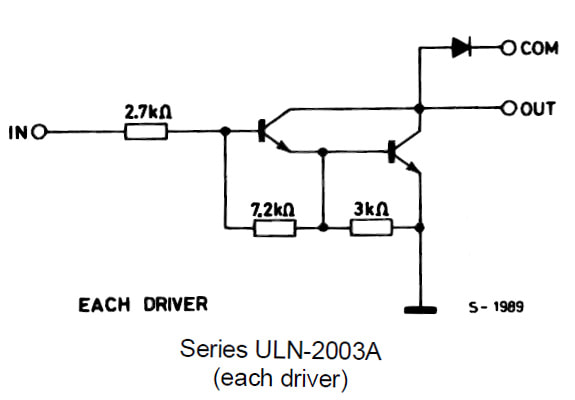
​Individual darlington pair configuration in ULN2003 ic is given on the right side. 3.3 volts from the output pins of stm32 microcontroller goes to the base of first transistor. First transistor emitter is input to second transistor base. So when first transistor is switched on instantly the second will also becomes switched on. Current will start flowing from ‘Out’ to ground. Diode at the ‘COM’ pin is working as a fly back diode. It prevents the circuit from any back emf generated by the relay coils. ULN2003 can handle loads requiring 50 volts and 500 mA of current.    

Picture

Single uln2003 darlington transistor pair circuit

Project Circuit

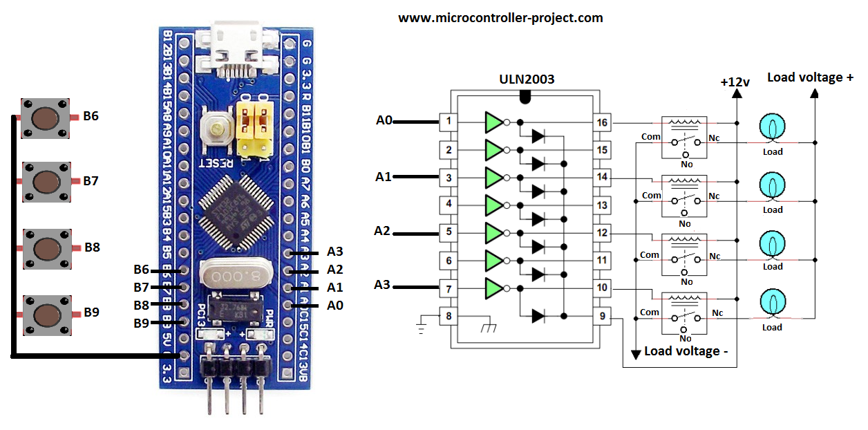
I am going to switch on and off four relays with stm32 microcontroller. Four buttons are used as input to stm32 microcontroller. These four buttons corresponds to four output relays. Pressing each button will change the state of its corresponding relay. For example if the relay is on pressing its corresponding button will change its state to off. We can say that buttons are toggling the state of relays on each press.

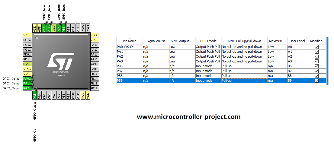
Microcontroller used in the project is stm32f103c8t6. Its build on cortex m3 core. Port-A pins 0,1,2,3 of stm32 microcontroller are used as output pins. Pin#0 of port-a is connected to input 1 of ULN2003 relay driver. Pin#1 of port-a is connected to input 3, pin#2 is connected to input 5 and pin#3 is connected to pin#7 of ULN2003 relay driver.
​
Input buttons are connected to port-b pins 6, 7, 8, 9. Stm32 microcontroller has build in pull up and pull down resistors on each individual gpio pin. We can enable and disable them in code. For our button inputs i enabled the pull up resistors associated with each gpio(Port-B Pin#6,7,8,9). One side of input buttons is connected to microcontroller pins and the other side is commonly grounded.

Relays which i am using in the project activates on +9 volts. I connected the relay coil one end with ULN2003 output and the other +12 volts. Com pin of relay is grounded with the load power. Nc pin of relay is connected with load and other end of load is connected with positive lead of load power. No pin of relay is left untouched. Ground pin of ULN2003 is grounded with relay 12 volt power supply and with stm32 ground. Note ULN2003 GND must be commonly grounded with stm32 power supply and ULN2003 relay power supply.  

Relays with stm32 microcontroller and uln2003 relay driver

Relays with stm32 microcontroller and uln2003 relay driver

Project Code

Stm32cubemx is used for microcontroller configuration. Input and output pins are declared in it. Pull up and pull down resistor on input pins are also activated in stm32cubemx. After the configuration and settings project code is created and imported for keil uvision arm 5 mdk ide. Below fig is the final stm32 settings in stm32cubemx. 

Stm32cubemx GPIOS settings for pins as input and output

Stm32cubemx GPIOS settings for pins as input and output
If you did not worked with stm32cubemx code configurator and keil uvision mdk arm 5 and you are newbe in this field. Than i have a comprehensive getting started tutorial on stm32 cubemx and keil ide for you. Click the below button for tutorial.

Getting started with stm32cubemx and keil arm mdk

Code is written and compiled in keil uvision ide. Stm32 HAL libraries are used in the project. Main logic and crux of the code is in the while 1 loop. The statement

if(HAL_GPIO_ReadPin(GPIOB,B6_Pin)==GPIO_PIN_RESET) //Check for input button press 

is checking if the button is pressed or not. The statement utilizes stm32 HAL libraries for checking the state of the input button. Port-B Pin#6 is checked in the above code. GPIO_PIN_RESET means if the pin is at low voltage(0 volts). When the button is pressed the ground appears on this pin. Since the button other end is connected to stm32 ground. If the above statement is true the next statement is executed.  

HAL_GPIO_TogglePin(GPIOA,A0_Pin);

Above statement executes right after the if statement IF if statement is true. It toggles the state of relay. This statement also utilizes stm32 HAL libraries. The statement toggles the state of port-a pin#6.   
Making the above circuit on bread board is hard for a diy project. If you are making a diy project on stm32 relay driving. I suggest you to use a pre assembled relay board in your project. There are numerous relay boards available in market containing different number of relays. 2 channel, 4 channel and 8 channel relay boards are most commonly available in market. These boards have ULN2003 or ULN2803 relay driver ic’s installed on them. They also have status led’s on them. Led’s depicts the status of relays. Terminal blocks for each relay are also very help full in making connections with loads.
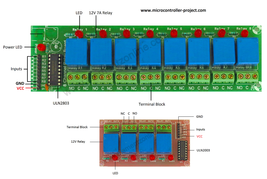
The code above can be used with the relay board. Connections are same. Only you have to make relay power and stm32 power grounds common.  

4 channel or 8 channel relay board for microcontroller with uln2003 and uln2803 relay driver

4 channel or 8 channel relay board for microcontroller with uln2003 and uln2803 relay driver
Relay boards also comes with optocouplers and single transistor circuits. The code in this project can be used with any of the relay board containg ULN2003, ULN2803, optocouplers or individual transistors as relay drivers.  
Code/Files

You may also like:


  • What are EMS/EMC immunity lab tests?

  • What are the different EV charging protocols?

  • What battery chemistries are used in electric vehicles?

  • What’s a protective relay and what does it protect?

  • What is an Actuator Sensor Interface (AS-i)?

  • What is the LoRaWAN network and how does it work?

Filed Under: Electronic Projects, STM32


Next Article

← Previous Article
Next Article →

Questions related to this article?
👉Ask and discuss on EDAboard.com and Electro-Tech-Online.com forums.


Tell Us What You Think!! Cancel reply

You must be logged in to post a comment.

EE TECH TOOLBOX

“ee
Tech Toolbox: 5G Technology
This Tech Toolbox covers the basics of 5G technology plus a story about how engineers designed and built a prototype DSL router mostly from old cellphone parts. Download this first 5G/wired/wireless communications Tech Toolbox to learn more!

EE Learning Center

EE Learning Center
“engineers
EXPAND YOUR KNOWLEDGE AND STAY CONNECTED
Get the latest info on technologies, tools and strategies for EE professionals.

HAVE A QUESTION?

Have a technical question about an article or other engineering questions? Check out our engineering forums EDABoard.com and Electro-Tech-Online.com where you can get those questions asked and answered by your peers!


RSS EDABOARD.com Discussions

  • Inconsistent Charge Termination Voltage with battery charger
  • 21V keeps getting shorted to my UART line.
  • Voltage mode pushpull is a nonsense SMPS?
  • Voltage mode push pull with extra DC blocking capacitor
  • NXP library issue in awr

RSS Electro-Tech-Online.com Discussions

  • Is AI making embedded software developers more productive?
  • Why can't I breadboard this oscillator?
  • using a RTC in SF basic
  • Parts required for a personal project
  • Cataract Lens Options?

Featured – RPi Python Programming (27 Part)

  • RPi Python Programming 21: The SIM900A AT commands
  • RPi Python Programming 22: Calls & SMS using a SIM900A GSM-GPRS modem
  • RPi Python Programming 23: Interfacing a NEO-6MV2 GPS module with Raspberry Pi
  • RPi Python Programming 24: I2C explained
  • RPi Python Programming 25 – Synchronous serial communication in Raspberry Pi using I2C protocol
  • RPi Python Programming 26 – Interfacing ADXL345 accelerometer sensor with Raspberry Pi

Recent Articles

  • GigaDevice launches GD32C231 MCU series with 48MHz Cortex-M23 core and 64KB Flash
  • Advanced Energy releases 425 W CF-rated medical power supply in 3.5 x 6 x 1.5-inch format”
  • LEM combines shunt and Hall effect sensing in 2000 A current measurement unit
  • What is AWS IoT Core and when should you use it?
  • AC-DC power supply extends voltage range to 800 V DC

EE ENGINEERING TRAINING DAYS

engineering

Submit a Guest Post

submit a guest post
Engineers Garage
  • Analog IC TIps
  • Connector Tips
  • Battery Power Tips
  • DesignFast
  • EDABoard Forums
  • EE World Online
  • Electro-Tech-Online Forums
  • EV Engineering
  • Microcontroller Tips
  • Power Electronic Tips
  • Sensor Tips
  • Test and Measurement Tips
  • 5G Technology World
  • Subscribe to our newsletter
  • About Us
  • Contact Us
  • Advertise

Copyright © 2025 WTWH Media LLC. All Rights Reserved. The material on this site may not be reproduced, distributed, transmitted, cached or otherwise used, except with the prior written permission of WTWH Media
Privacy Policy

Search Engineers Garage

  • Electronic Projects & Tutorials
    • Electronic Projects
      • Arduino Projects
      • AVR
      • Raspberry pi
      • ESP8266
      • BeagleBone
      • 8051 Microcontroller
      • ARM
      • PIC Microcontroller
      • STM32
    • Tutorials
      • Audio Electronics
      • Battery Management
      • Brainwave
      • Electric Vehicles
      • EMI/EMC/RFI
      • Hardware Filters
      • IoT tutorials
      • Power Tutorials
      • Python
      • Sensors
      • USB
      • VHDL
    • Circuit Design
    • Project Videos
    • Components
  • Articles
    • Tech Articles
    • Insight
    • Invention Stories
    • How to
    • What Is
  • News
    • Electronic Product News
    • Business News
    • Company/Start-up News
    • DIY Reviews
    • Guest Post
  • Forums
    • EDABoard.com
    • Electro-Tech-Online
    • EG Forum Archive
  • DigiKey Store
    • Cables, Wires
    • Connectors, Interconnect
    • Discrete
    • Electromechanical
    • Embedded Computers
    • Enclosures, Hardware, Office
    • Integrated Circuits (ICs)
    • Isolators
    • LED/Optoelectronics
    • Passive
    • Power, Circuit Protection
    • Programmers
    • RF, Wireless
    • Semiconductors
    • Sensors, Transducers
    • Test Products
    • Tools
  • Learn
    • eBooks/Tech Tips
    • Design Guides
    • Learning Center
    • Tech Toolboxes
    • Webinars & Digital Events
  • Resources
    • Digital Issues
    • EE Training Days
    • LEAP Awards
    • Podcasts
    • Webinars / Digital Events
    • White Papers
    • Engineering Diversity & Inclusion
    • DesignFast
  • Guest Post Guidelines
  • Advertise
  • Subscribe