This project based on DTMF (Dual Tone multi frequency) which is generated in cellular phones. Here, by using a cell phone we controls the home appliances from anywhere in the world (In Network Area). Below you can see the diagram of DTMF keypad. When we press any key then it generates a frequency after mixing two frequencies. And then send it to the receiver end over communication channel.


Circuit Designing
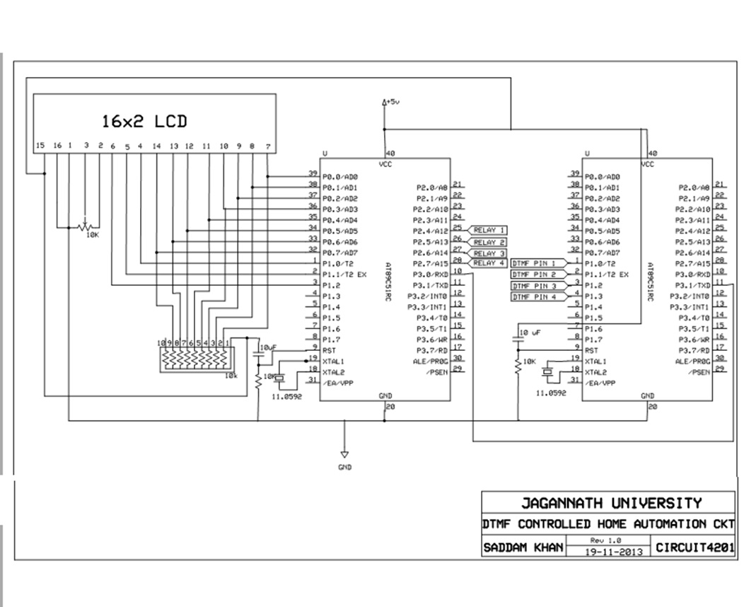
Circuit:


PCB Images


Project Source Code
###
****************************DTMF RECEIVER************************* #include<reg51.h> #include<string.h> #define all_on P2=0xf0 #define all_off P2=0x00 #define dataport P0 #define cmdport P1 #define output P2char y;int k;
sbit rs=cmdport^0;
sbit rw=cmdport^1;
sbit en=cmdport^2;
sbit tv=output^0;
sbit fan=output^1;
sbit light=output^2;
sbit ac=output^3;char compare1[4]="4211"; // TV ON
char compare2[4]="4212"; // FAN ON
char compare3[4]="4214"; // LIGHT ON
char compare4[4]="4204"; // AC ON
char compare5[4]="4210"; // TV OFF
char compare6[4]="4212"; // FAN OFF
char compare7[4]="4213"; // LIGHT OFF
char compare8[4]="4214"; // AC OFF
char compare9[4]="4205"; // ALL ON
char compare0[4]="4215"; // ALL OFF
char input[4]; //input stringvoid delay(int time)
{
unsigned int i,j;
for(i=0;i<time;i++)
for(j=0;j<1275;j++);
} // delay funtionvoid lcddata(char item)
{
dataport=item;
rs=1,rw=0,en=1;
delay(5),en=0;
} // funtion to send data to lcdvoid print(char cmd, char *str)
{
dataport=cmd;
rs=0,rw=0,en=1;
delay(5),en=0; // funtion to send cmd and print data to lcd
while(*str!='�')
{
lcddata(*str);
str++;
}
}void LCD_clear()
{
delay(50);
print(0x01,0);
}
// funtion to clear lcd
void LCD_Init() // funtion to LCD initialize
{
print(0x38,0);
print(0x06,0);
print(0x0e,0); // print introduction on lcd
print(0x80," A PROJECT BY ");
print(0xc0," SADDAM KHAN ");
LCD_clear();
print(0x80,"DTMF CONTROLLED ");
print(0xc0,"HOME AUTOMATION ");
LCD_clear();
print(0x80," SYSTEM READY ");
}void serial_init()
{
TMOD=0X20;
SCON=0X50;
TH1=0XFD;
TR1=1;
} // funtion to initialize serial communication
void main() // main program
{
all_off;
serial_init();
LCD_Init(); // initiaze lcd and serial communication
while(1)
{
print(0xC0,"ENTER CODE "); // enter a string of length 4 by using for loop
for(k=0;k<4;k++)
{
while(RI==0);
y=SBUF;
input[k]=y;
lcddata(input[k]);
RI=0;
delay(40);
}
if(strcmp(compare1, input)==0) // compare input strings with stored strings
{LCD_clear();print(0x80," TV ON ");tv=1;}
if(strcmp(compare2, input)==0)
{LCD_clear();print(0x80," FAN ON ");fan=1;}
if(strcmp(compare3, input)==0)
{LCD_clear();print(0x80," LIGHT ON ");light=1;}
if(strcmp(compare4, input)==0)
{LCD_clear();print(0x80," AC ON ");ac=1;}
if(strcmp(compare5, input)==0)
{LCD_clear();print(0x80," TV OFF ");tv=0;}
if(strcmp(compare6, input)==0)
{LCD_clear();print(0x80," FAN OFF ");fan=0;}
if(strcmp(compare7, input)==0)
{LCD_clear();print(0x80," LIGHT OFF ");light=0;}
if(strcmp(compare8, input)==0)
{LCD_clear();print(0x80," AC OFF ");ac=0;}
if(strcmp(compare9, input)==0)
{LCD_clear();print(0x80," ALL ON ");all_on;}
if(strcmp(compare0, input)==0)
{LCD_clear();print(0x80," ALL OFF ");all_off;}}
}
******************DTMF TRANSMITTER******************#include<reg51.h>
sbit led=P2^0;char k;void delay(int time)
{unsigned int i,j;
for(i=0;i<time;i++)
for(j=0;j<1000;j++);}void serial_init()
{TMOD=0X20;
SCON=0X50;
TH1=0XFD;
TR1=1;}void transmit(char k)
{SBUF=k;
while(TI==0);
TI=0;}void main()
{
P1=0xff;
serial_init();
delay(500);
while(1)
{P1=0xff;
if(P1==0xf1){transmit('1');while(P1==0xf1);delay(20);}
if(P1==0xf2){transmit('2');while(P1==0xf2);delay(20);}
if(P1==0xf3){transmit('3');while(P1==0xf3);delay(20);}
if(P1==0xf4){transmit('4');while(P1==0xf4);delay(20);}
if(P1==0xf5){transmit('5');while(P1==0xf5);delay(20);}
if(P1==0xfa){transmit('0');while(P1==0xfa);delay(20);}
}
}###
Circuit Diagrams
Project Datasheet
Project Video
Filed Under: Electronic Projects
Filed Under: Electronic Projects

Questions related to this article?
👉Ask and discuss on Electro-Tech-Online.com and EDAboard.com forums.
Tell Us What You Think!!
You must be logged in to post a comment.