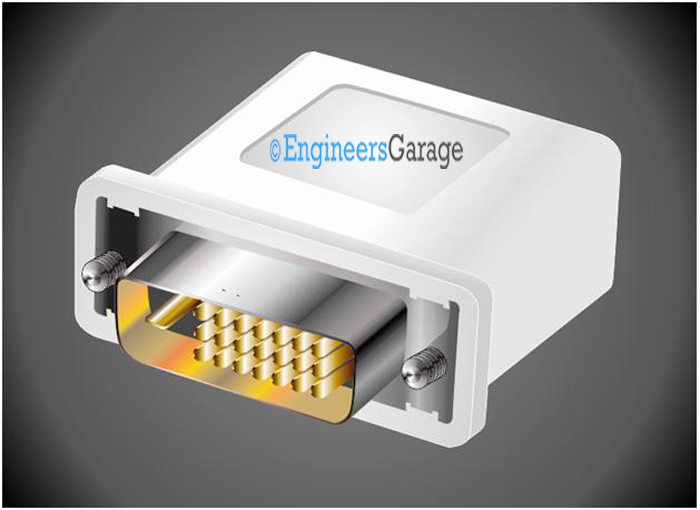
DVI stands for digital video interface and it is designed for the interfacing of a video device to usually a high definition display device. This is an industrial standard for the transmission of digital video content and the DVI standard is developed by the Digital Display Working Group (DDWG) in April 1999. DVI is a hot pluggable external interface for the PC with a 29 pin connector. The DVI connector has both male and female types.

Fig. 1: Image of a male DVI connector

Fig. 2: Image of a female DVI connector
DVI Connector Designs
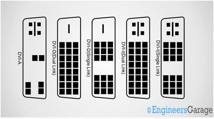
The DVI connector designs are available for different modes of video transmissions. The DVI-D connector is designed to support digital video signals only, DVI-A supports analog video signals only and DVI-I can transmit both digital and analog video signals at the same time.
The connector diagrams for the DVI-D, DVI-A and DVI-I connectors for dual link and single link are shown in the following figure.

DVI connectors are commonly found in devices with flat panel display like television with LCD screen, plasma screen etc. They are also used in DVD players, video projectors etc.
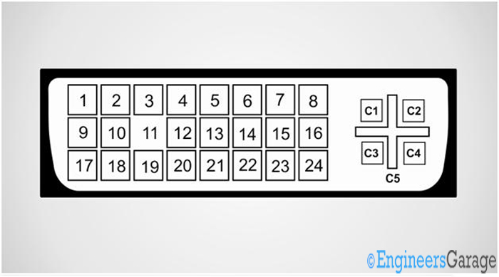
The pin position of a 29 pin female DVI-I connector from the front is shown in the following image.

Fig. 4: Image showing pin position of female DVI-I
The pin-out of the 29 pin DVI-D connector
PIN 1 —————— TMDS data 2?
PIN 2 —————— TMDS data 2+
PIN 3 —————— TMDS data 2/4
PIN 4 —————— TMDS data 4?
PIN 5 —————— TMDS data 4+
PIN 6 —————— DDC clock
PIN 7 —————— DDC data
PIN 8 —————— Analog vertical sync
PIN 9 —————— TMDS data 1?
PIN 10 —————– TMDS data 1+
PIN 11 —————– TMDS data 1/3
PIN 12 —————– TMDS data 3-
PIN 13 —————– TMDS data 3+
PIN 14 —————– +5 V
PIN 15 —————– Ground
PIN 16 —————– Hot plug detect
PIN 17 —————– TMDS data 0?
PIN 18 —————– TMDS data 0+
PIN 19 —————– TMDS data 0/5
PIN 20 —————– TMDS data 5?
PIN 21 —————– TMDS data 5+
PIN 22 —————– TMDS clock
PIN 23 —————– TMDS clock+
PIN 24 —————– TMDS clock?
C1 ———————– Analog red
C2 ———————– Analog green
C3 ———————– Analog blue
C4 ———————– Analog horizontal sync
C5 ———————– Analog ground
Sample specification & Summary
Sample specification:
Rated current ————————— 1.5 A
Rated voltage ————————— 40 VAC
Contact resistance ——————— 30 m? max.
Insulation resistance —————— 1,000 M? min
Withstand voltage ——————— 500 VDC for 1 min.
Ambient temperature —————– 20°C to 85°C
Summary
{C}{C}{C}{C}{C}· {C}{C}{C}{C}{C}Digital Video Interface (DVI) connector is an industrial standard connector for the transmission of digital video content
{C}{C}{C}{C}{C}· {C}{C}{C}{C}{C}The DVI standard includes DVI-A for analog video signals only, DVI-D for digital video signals only and DVI-I which for combined digital and analog video signals.
{C}{C}{C}{C}{C}· {C}{C}{C}{C}{C}The DVI connectors are commonly used in HDTV, DVD, video projectors, LCD and plasma screens.
Filed Under: Tutorials


Questions related to this article?
👉Ask and discuss on Electro-Tech-Online.com and EDAboard.com forums.
Tell Us What You Think!!
You must be logged in to post a comment.