E-cricket is acool game circuit.
This can be play by two or more members
This game is same like a cricket games which we see or play in ground.
E-cricket is very easy to play, it can be played by any age group people and at the same time it is so much interesting game to play.
As this circuit contains few components, this circuit is small in size. So it is easy to carry this game with you all the time and play whenever u got time.
You can also play this game in picnics, parties or any gathering.
Principle behind E-Cricket Circuit-
This circuit is mainly for cricket lovers who watch cricket game and want to play, but unable to play due to their phatic schedule or any reasons.
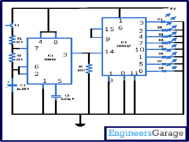
E-Cricket circuit shows various stages of cricket like out, six and many more with the help of various LED’s.
At the time when S1 (which is push to on switch) pressed for a moment of time, the astable gets into work. As a result of it all the LEDs starts blinking in high speed.And as soon as S1 is free, one of the LED starts glowing which specifies the position of the game.Suppose D3 remains on, it designates as four and if D1 remains on, it designates as bowled.
Designates each LED one status as Shown below-
| Pin1 | D6 | Single run |
| Pin2 | D2 | 2 run |
| Pin3 | D1 | Bowled |
| Pin4 | D3 | 4 run |
| Pin5 | D7 | Six |
| Pin6 | D8 | wide |
| Pin7 | D4 | catch |
| Pin8 | D5 | No ball |
Note- You can designate different status to LEDs. For example D2 can be six like wise.
Pressing of button is a sign of bowling while fast alternating of LEDs directs that batsman is running.
In this circuit IC1 (NE555) is coupled in astable mode along with resistors (R1 and R2) and capacitor (C1) which act as a timing element. Too fast output pulses are produced from the astable due to the components presented values. IC2 CD4017 gets the input from IC1 pin 3.IC2 is a 16 pin IC in which pin 14 is for input and 10 pins for output. IN this circuit we have used 8 pins (i.e. pin 1, 2, 3, 4, 6, 7, 10) for receiving output. For repeating cycle pin 15(which is a reset pin) is connected with pin 9 (it is also an output pin).At the time when IC2 pin 14 receives pulses from low to high state, its output switches to high one by one. For escaping wrong indication resistor R3 holds the IC2 input low in stand by condition.
To slow down LEDs blinking when S2 pressed, you can increase the value of C2.
(Note- In this circuit no resistors are connected with LEDs because around 1.7 V of voltage passes through LED so there is no risk LEDs to get burn. If you want you can attach one 100K of resistor with all LEDs).
Circuit Diagrams
Project Components
Filed Under: Circuit Design


Questions related to this article?
👉Ask and discuss on Electro-Tech-Online.com and EDAboard.com forums.
Tell Us What You Think!!
You must be logged in to post a comment.