Electricity theft is a common problem. Due to electricity theft, not only there are losses to the revenue of the government but over loading and damage to the transformers is an unwanted consequence of the theft as well. This project is an attempt to resolve electricity theft problem. The project detects the theft by detecting over loading at the transformer. Once the over loading is detected, a relay circuit is employed to shut down the power supply from the respective transformer. Definitely, power shut down on doing electricity theft will discourage the mischievous elements.
The project demonstrated here is to show the mechanism of electricity anti-theft system. A pack of parallel connected bulbs is used as load while the programmable circuit operating the supply controlling relay is based on Arduino. The principle used behind detecting overloading is voltage comparison and an additional buzzer circuit is attached to the project to alert electricity theft in the locality. The buzzer mechanism has been added to alert people of electricity theft and demoralize the mischievous elements.
The project has the following execution cycle:
1) The project will be connected at the primary coil of an additional transformer which will have its secondary coil connected between the main line and loads while the loads (a pack of bulbs is used as load in the demonstration) will be connected to the main line via relay interfaced to main line through secondary coil of the additional transformer. This additional transformer shall work like a voltage sensor in the circuit.
2) The Arduino based circuit will show the status of the main line as overloaded or not on an LCD display. The LCD display section is however optional and added for testing and demonstration purpose only.
3) When system detects over load condition which will be transferred as a HIGH signal to the voltage comparator interfaced pin of Arduino, the board will output signals to trigger the relay circuit.
4) The relay will cut off the power supply from the main line and the whole system will get shut down.
5) After a shut down the system will wait for conditions to normalize and will resume the power supply as unauthorized loads are detached and relevant voltage is detected at the primary of transformer-based sensor circuit.
Components Required:
1) Arduino UNO
2) Transformer 12 – 0v
3) Buzzer
4) 16×2 LCD
5) 12v Relay
6) BC 547 transistor
7) 1K ohm resisters -7
8) Voltage regulator -7805
9) LED -5mm RED- 2
10) Wire to carry 2A, 230v AC
11) Two pin Plug
12) Bulb holder.
Block Diagram:

Fig. 1: Block Diagram of Electricity Anti-Theft System
Circuit Connections –
As clear from the block diagram the project has the following circuits integrated together:
1) Power Supply Regulator
2) Transformer based sensor circuit
3) LCD Display
4) Relay Circuit as Power Switching Unit
5) Arduino Board
The Arduino Board is the programmable Unit that will be controlling the entire functionality of the circuit and every module will be interfaced to it. The circuit will be connected the following way-
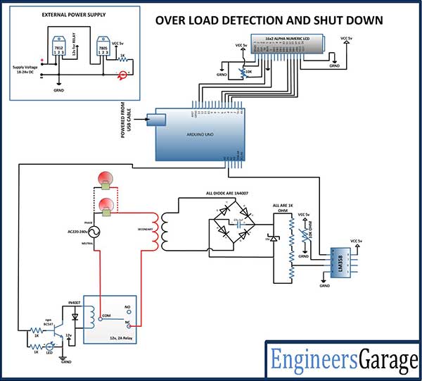
1) Power Supply: While the loads will be running on AC supply, the project circuit will require 12V and 5V DC supply. The 12V supply will be provided via a 12V DC Battery and will be provided to 12V relay and 7805 voltage regulator. The other components will need a 5V DC supply which will be provided via 7805 voltage regulator that is converting the input 12V supply to 5V DC.
2) Transformer as Sensor: It is well known that transformer works on the principle of mutual induction. The loads (bulbs in this case) are connected through the secondary coil of the transformer with the main line and are parallel connected. This is similar to wiring system of houses in which all the power sockets have parallel connections with the main supply. Therefore, in any house all the electrical appliances are basically connected in parallel. When the loads (bulbs) starts conducting current, the current also flows the secondary coil added transformer and due to mutual induction, some voltage is induced at the primary coil of the added transformer. The voltage induced increases as the more number of loads are connected to the main line. The voltage gain is feed to the comparator circuit. The comparator circuit compares the change in voltage and sends a HIGH logic to the connected pin of the Arduino board.

Fig. 2: Circuit Diagram showing Transformer as Overload Detector
3) LCD Display: The 16X2 LCD display is connected to the Arduino board by connecting its data pins to pins 3 to 6 of the Arduino board. The RS and E pin of LCD is connected to pins 12 and 13 of the Arduino UNO respectively. The RW pin of the LCD is grounded.

Fig. 3: Table listing circuit connections between Arduino Uno and Character LCD
The standard code library for interfacing Arduino UNO and Arduino Pro Mini are used in the project to program LCD with the board.
4) Relay Circuit: The loads are connected to the main line via a 12V relay. The relay is connected to the pin A0 of Arduino board through BC547 transistor circuit which is in a common emitter configuration.
How the Circuit Works –
The circuit works in following stages:
1) Initialization of the circuit –
As the circuit is switched on Arduino loads the imported libraries and initialize LCD display and the relay circuit. First Initial messages are flashed on the display screen showing no overloading condition and data from voltage comparator is fetched from the A1 pin of Arduino UNO board. A LOW signal is set at the pin 10 of Arduino UNO connected to the relay which switches the relay to an ON state and keeps the power supply through main line ON.
2) Switching Relay – While continuous polling logic from the voltage comparator, at an instance, voltage at A1 pin of Arduino UNO gets greater than the reference voltage. This prompts the Arduino board to set a HIGH signal at pin 10. An LED connected parallel to the relay lights on to alert that the overloading condition. The relay is connected to the pin 10 via transistor BC547. The BC547 is configured in common emitter configuration. The base of the transistor is connected to pin 10 through a 1K ohm resistor and collector of the transistor is connected to the relay coil. The emitter is grounded. When a HIGH signal is received from pin 10, current starts flowing from base to emitter and collector becomes grounded. The other end of the relay coil is connected to 12V supply, thus as collector is grounded current starts flowing through the relay coil and the device is cut short of the power supply.
Programming Guide –
The code utilizes standard open source libraries of the Arduino UNO. Therefore, first of all the standard library for LCD is imported and a variable ‘relay’ is declared which is assigned to pin A2 of the Arduino board.

Fig. 4: Screenshot of initialization in Arduino Code for Electricity Anti-Theft System
A setup() function is called where the relay and buzzer connected pins are set to digital output using pinMode() function and a LOW is passed to the respective pins through digitalWrite() function. The lcd is initialized and initial messages are flashed on it.

Fig. 5: Screenshot of Setup Function in Arduino Code for Electricity Anti-Theft System
A loop() function is called where analog value of the voltage from voltage comparator is fetched and compared to a standard calibrated voltage range and if there is overloading detected, relay is operated to cut off the supply line, buzzer is set to alert and overloading message is displayed on the screen.

Fig. 6: Screenshot of Loop Function in Arduino Code for Electricity Anti-Theft System
Project Source Code
###
//Program to #include <LiquidCrystal.h>//import the LCD library LiquidCrystal lcd(13, 12, 6, 5, 4, 3);// Pins used for RS,E,D4,D5,D6,D7 int x; #define relay 7 #define buzzer 10 void setup() { lcd.begin(16,2);//LCD 16x2 initialization pinMode(relay, OUTPUT); pinMode(buzzer, OUTPUT); digitalWrite(buzzer, LOW); digitalWrite(relay, LOW); lcd.setCursor(0,0); //Initially set the cursor position of LCD to 1st Columb 1st row. lcd.print("Engineers Garage");//After initialising print data lcd.setCursor(0,1); //Initially set the cursor position of LCD to 1st Columb 2nd row. lcd.print(" "); //print blank to clear all the data on LCD delay(3000); lcd.setCursor(0,0); lcd.print(" LOAD DETECTION "); lcd.setCursor(0,1); lcd.print(" AND SHUTDOWN "); delay(3000); lcd.setCursor(0,0); lcd.print(" "); lcd.setCursor(0,1); lcd.print(" "); } void loop() { x=analogRead(A0)*(5.0/1023.0)*100; lcd.setCursor(0,0); lcd.print(" OVER LOAD "); lcd.setCursor(0,1); lcd.print(" DETECTION "); lcd.setCursor(13,1); lcd.print(x); if(x>385 && x <470){ digitalWrite(relay, HIGH); lcd.setCursor(0,0); lcd.print(" LOAD DETECTED "); lcd.setCursor(0,1); lcd.print(" "); for(int i=0;i<3;i++){ digitalWrite(buzzer,HIGH); delay(500); digitalWrite(buzzer,LOW); delay(500); } } else if(x<280){ digitalWrite(relay, LOW); } else; } // end loop###
Circuit Diagrams
Filed Under: Electronic Projects

Questions related to this article?
👉Ask and discuss on Electro-Tech-Online.com and EDAboard.com forums.
Tell Us What You Think!!
You must be logged in to post a comment.