Replacing vacuum tubes with transistors made it possible to switch between logic states with a minute amount of power consumption and in a relatively smaller space. This article will focus on logic switching.
Not much has changed with electrical switching technologies, although there have been some innovations around various techniques to switch electrical loads. Still, the size and power of devices used for electrical switching are much bigger than their logic switching counterparts.
The most popular electrical switching component known is a relay. On its own, it consumes much less power than the heavy-duty load it can drive. A relay’s driver and load are isolated from each other to ensure against mishaps to the control system.
We can classify relays into two categories
- Electromechanical
- SSR (Solid-State Relays)
Generally, relays are electromechanical, whereby a solid wire makes contact and allows current to pass through it, usually short-circuiting the wire at the output. The relays working on this principle are the most familiar. They perform best in cases where delay doesn’t matter, and switching frequency is low. But what about the cases where a delay is critical, and high switching activity is required? This is where SSRs are well suited. SSRs switch the output without any mechanical part involvement and use multiple techniques to drive the output without any physical contact.
Solid-state relays (SSR)
Unlike regular relays, solid-state relays don’t have any mechanical parts, so they produce no noise during switching. Removing the mechanical element increases the switching speed allowing the relays to work on higher frequencies. Solid-state relays adhere to all other relay properties (isolation, heavy load driving, etc.) from their mechanical family members. Most common solid-state relays work on the optoisolation principle, where input and output are separated based on light.
What is optoisolation?
Optoisolation or optocoupling is a technique in which a light-dependent resistor (LDR) activates an output when its surface is exposed to a light source. In the case of solid-state relays, we have an LED at the input and a light-dependent resistor at the output. The light-dependent resistor at the output is part of a circuit composed of several other electronic components, such as a transistor, diode, MOSFET, SCR, DIAC, or TRIAC.
For example,

Figure 1. An internal structure of an SSR.
The above SSR has an LED at the input and a MOSFET at the output. The LDR is not shown in the above circuit diagram, but it lies between the base of the two MOSFETs. When the light from the LED falls on the LDR, the resistance of the LDR decreases, and a short circuit allows the current to flow between the output channels. The SSR in Figure 1 can handle a load current of a few milliamperes.
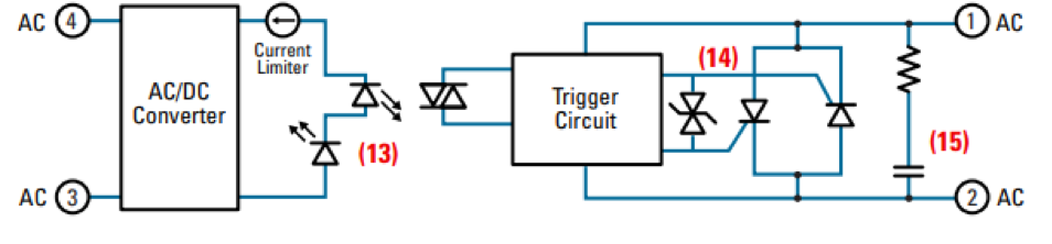
Figure 2. An example of another SSR.
The SSR internal structure shown in Figure 2 is separated using an optoisolator. At the output side, we now have several other components, such as the opto triac and SCR. The SSR above can handle current in amperes; as the SSR output power handling increases, the internal structure becomes increasingly more complex.
The key advantages of SSRs over traditional relays are:
- Non-mechanical switching.
- Almost no switching noise.
- The switching frequency is high compared to conventional relays.
- Optoelectronic isolation.
- Low input power consumption (just an led at the input. whereas traditionally a coil).
- Drive heavy loads, used in heavy industrial processes where heavy-duty motors are working on high frequencies
- Works on both AC and DC voltage.
The key disadvantages of SSRs over traditional relays are:
- The SSR heats up too quickly, so an extra heat sink is required to absorb the heat. This increases the bill of materials.
- While it is not necessarily a disadvantage, it does matter in certain applications. Because of the size and weight of SSRs, it’s difficult to mount them on a PCB, and extra space is required to house them.
How to build your SSR
Yes, it’s possible to build up an SSR from scratch. A simple SSR circuit is shown in Figure 3.
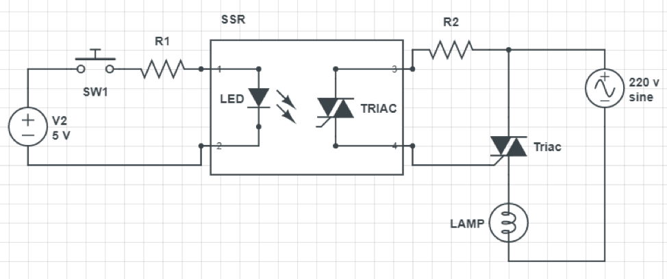
Figure 3 Made on circuitlab.com
The central part of your custom SSR will be a photocoupler. We suggest you choose a photocoupler with an output driven by a TRIAC, as shown in Figure 3. The SSR inputs can be controlled with a microcontroller or a digital circuit. Heavy-duty applications include inputs from a PLC (programmable logic controller) or VFD (variable frequency drivers). A Schmitt trigger circuit can also drive the SSR, although it’s best to use a Schmitt architecture when power is critical.
You can directly attach your loads or extend the circuit according to your requirements at the output of the SSR pins. For testing purposes, a bulb at the output is preferable, where a bulb is driven by a TRIAC working on an AC power supply.
You may also like:
Filed Under: Featured, Tutorials

Questions related to this article?
👉Ask and discuss on EDAboard.com and Electro-Tech-Online.com forums.
Tell Us What You Think!!
You must be logged in to post a comment.