Engineers Garage

  • Electronic Projects & Tutorials
    • Electronic Projects
      • Arduino Projects
      • AVR
      • Raspberry pi
      • ESP8266
      • BeagleBone
      • 8051 Microcontroller
      • ARM
      • PIC Microcontroller
      • STM32
    • Tutorials
      • Audio Electronics
      • Battery Management
      • Brainwave
      • Electric Vehicles
      • EMI/EMC/RFI
      • Hardware Filters
      • IoT tutorials
      • Power Tutorials
      • Python
      • Sensors
      • USB
      • VHDL
    • Circuit Design
    • Project Videos
    • Components
  • Articles
    • Tech Articles
    • Insight
    • Invention Stories
    • How to
    • What Is
  • News
    • Electronic Product News
    • Business News
    • Company/Start-up News
    • DIY Reviews
    • Guest Post
  • Forums
    • EDABoard.com
    • Electro-Tech-Online
    • EG Forum Archive
  • DigiKey Store
    • Cables, Wires
    • Connectors, Interconnect
    • Discrete
    • Electromechanical
    • Embedded Computers
    • Enclosures, Hardware, Office
    • Integrated Circuits (ICs)
    • Isolators
    • LED/Optoelectronics
    • Passive
    • Power, Circuit Protection
    • Programmers
    • RF, Wireless
    • Semiconductors
    • Sensors, Transducers
    • Test Products
    • Tools
  • Learn
    • eBooks/Tech Tips
    • Design Guides
    • Learning Center
    • Tech Toolboxes
    • Webinars & Digital Events
  • Resources
    • Digital Issues
    • EE Training Days
    • LEAP Awards
    • Podcasts
    • Webinars / Digital Events
    • White Papers
    • Engineering Diversity & Inclusion
    • DesignFast
  • Guest Post Guidelines
  • Advertise
  • Subscribe

Electronic Circuit Breaker

By D.Mohankumar April 21, 2008


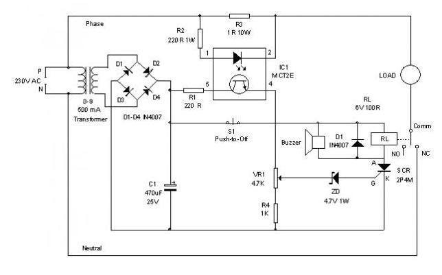
This circuit can sense the overload condition and breaks the power if the load increases above the set point. It is an ideal circuit to protect Uninterrupted Power Supply devices like Inverter.
Electronic Circuit Breaker

Let us see its working …
The Optocoupler MCT2E and the Resistor R3 (1 Ohm 10 Watts) will do the trick. The Optocoupler has an LED and a Phototransistor inside with connecting leads. The LED of MCT2E is connected parallel to the resistor R3 with a current limiter R2 for the LED. The phototransistor of Optocoupler is connected to the transformer derived 9 volt DC through the current limiter R1. The load is connected through the Common and NC contacts of the relay. So it will work normally at power on. 
As the load switches on, current flows through R3 depending on the current drawingby the load. This changes the brightness of LED inside the Optocoupler which in turn control the biasing of the phototransistor. The emitter current of phototransistor thus depends on the brightness of LED which in turn depends on the current flowing through R3 to the load.
When the load current increases, a corresponding current flow increases through R3 and a corresponding potential difference develops across R3. When the load current increases maximum, Zener diode ZD conducts and triggers the SCR. The relay then turns on and breaks the supply to the load. When the relay turns on, the buzzer beeps to indicate the over load condition. The relay remains energized due to the latching action of SCR and it can be deenergized after removing the excess load and pressing S1. 
How to Set?
To set the circuit for the desired tripping point, use 100 watts bulbs as load. If maximum,300 watts is the desired tripping point, use three 100 watts bulbs as load and slowly adjust VR1 till relay energize and lamps turn off. At this point, buzzer beeps. Then remove one bulb and reset using S1. Load will switch on normally. Again connect the bulb. When it switches on, the relay will cut the load. With the given value of R3, maximum load allowable is 500 watts. If this point is required, use a 500 watts bulb for calibration. Use a suitable 10 or 15 Amps relay to handle the load.
Caution: At some points like transformer Primary and relay contacts, Lethal voltage exists, so adequate precautionary measures must be taken while testing the circuit. 


Circuit Diagrams

Electronic-Circuit-Breaker-


Filed Under: Electronic Projects
Tagged With: circuit breakers, electronic circuit breaker, led, Phototransistor, resistor
 

Next Article

← Previous Article
Next Article →

Questions related to this article?
👉Ask and discuss on Electro-Tech-Online.com and EDAboard.com forums.


Tell Us What You Think!! Cancel reply

You must be logged in to post a comment.

EE TECH TOOLBOX

“ee
Tech Toolbox: 5G Technology
This Tech Toolbox covers the basics of 5G technology plus a story about how engineers designed and built a prototype DSL router mostly from old cellphone parts. Download this first 5G/wired/wireless communications Tech Toolbox to learn more!

EE Learning Center

EE Learning Center
“engineers
EXPAND YOUR KNOWLEDGE AND STAY CONNECTED
Get the latest info on technologies, tools and strategies for EE professionals.

HAVE A QUESTION?

Have a technical question about an article or other engineering questions? Check out our engineering forums EDABoard.com and Electro-Tech-Online.com where you can get those questions asked and answered by your peers!


RSS EDABOARD.com Discussions

  • Monte-Carlo simulation error on ADE-XL
  • Identification of a 6 pin smd chip (sto-23-6) marked E2
  • Dynacord enter protect
  • IGBTs without negative gate drive
  • Need suggestions in task NI6363 retrigger (analog trigger)

RSS Electro-Tech-Online.com Discussions

  • Fun with AI and swordfish basic
  • using a RTC in SF basic
  • Does US electric code allow branching ?
  • Faulty heat air gun (dc motor) - problem to locate fault due to Intermittent fault
  • Sump pit water alarm - Kicad 9

Featured – LoRa/LoRaWan Series

  • What is the LoRaWAN network and how does it work?
  • Understanding LoRa architecture: nodes, gateways, and servers
  • Revolutionizing RF: LoRa applications and advantages
  • How to build a LoRa gateway using Raspberry Pi
  • How LoRa enables long-range communication
  • How communication works between two LoRa end-node devices

Recent Articles

  • How IoT network topologies work
  • The top five AI startups to watch in 2025
  • STMicroelectronics unveils SoC based on secure MCU
  • Nexperia’s 48 V ESD diodes support higher data rates with ultra-low capacitance design
  • Taoglas releases Patriot antenna with 18 integrated elements covering 600 to 6000 MHz

EE ENGINEERING TRAINING DAYS

engineering

Submit a Guest Post

submit a guest post
Engineers Garage
  • Analog IC TIps
  • Connector Tips
  • Battery Power Tips
  • DesignFast
  • EDABoard Forums
  • EE World Online
  • Electro-Tech-Online Forums
  • EV Engineering
  • Microcontroller Tips
  • Power Electronic Tips
  • Sensor Tips
  • Test and Measurement Tips
  • 5G Technology World
  • Subscribe to our newsletter
  • About Us
  • Contact Us
  • Advertise

Copyright © 2025 WTWH Media LLC. All Rights Reserved. The material on this site may not be reproduced, distributed, transmitted, cached or otherwise used, except with the prior written permission of WTWH Media
Privacy Policy

Search Engineers Garage

  • Electronic Projects & Tutorials
    • Electronic Projects
      • Arduino Projects
      • AVR
      • Raspberry pi
      • ESP8266
      • BeagleBone
      • 8051 Microcontroller
      • ARM
      • PIC Microcontroller
      • STM32
    • Tutorials
      • Audio Electronics
      • Battery Management
      • Brainwave
      • Electric Vehicles
      • EMI/EMC/RFI
      • Hardware Filters
      • IoT tutorials
      • Power Tutorials
      • Python
      • Sensors
      • USB
      • VHDL
    • Circuit Design
    • Project Videos
    • Components
  • Articles
    • Tech Articles
    • Insight
    • Invention Stories
    • How to
    • What Is
  • News
    • Electronic Product News
    • Business News
    • Company/Start-up News
    • DIY Reviews
    • Guest Post
  • Forums
    • EDABoard.com
    • Electro-Tech-Online
    • EG Forum Archive
  • DigiKey Store
    • Cables, Wires
    • Connectors, Interconnect
    • Discrete
    • Electromechanical
    • Embedded Computers
    • Enclosures, Hardware, Office
    • Integrated Circuits (ICs)
    • Isolators
    • LED/Optoelectronics
    • Passive
    • Power, Circuit Protection
    • Programmers
    • RF, Wireless
    • Semiconductors
    • Sensors, Transducers
    • Test Products
    • Tools
  • Learn
    • eBooks/Tech Tips
    • Design Guides
    • Learning Center
    • Tech Toolboxes
    • Webinars & Digital Events
  • Resources
    • Digital Issues
    • EE Training Days
    • LEAP Awards
    • Podcasts
    • Webinars / Digital Events
    • White Papers
    • Engineering Diversity & Inclusion
    • DesignFast
  • Guest Post Guidelines
  • Advertise
  • Subscribe