In this project, a digital dice will be designed. The objective of this project is to teach that how custom characters can be displayed on an LCD. In Arduino projects using 16X2 LCD for display, the characters can be directly printed on one of the two rows using print() function of the LCD library of Arduino. However, sometimes displaying custom characters on the LCD is the demand of the project. The same feature has been illustrated in this project by designing a digital dice.
A digital dice is a digital version of the regular dice. Any dice has six faces on which numbers from 1 to 6 are printed. On throwing a dice, one of the face and so one of the numbers between 0 and 7 appears on the upright face. It can be any random number between 0 and 7. The digital dice will also display a random number between 0 and 7 on every trial. When the project will be powered on, the LCD display will show a custom built “0” character. The trial will be simulated by pressing a switch on which a random number between 0 and 7 will be displayed on the 16X2 LCD. For the next trial, the LCD could be reset to display custom built “0” character on pressing another switch. Whenever custom character “6” will be randomly generated on LCD, a buzzer will start sounding to indicate that the user has got an additional trial.
The project is built on Arduino UNO and has a 16X2 LCD, a buzzer and a 2-switch keypad interfaced to it. The project code has been written Arduino IDE and burnt to the Arduino board through USB using AVR Dude.
COMPONENTS REQUIRED
1. Arduino UNO – 1
2. 16×2 LCD – 1
3. Buzzer – 1
4. BC547 Transistor – 1
5. Push to ON switches – 2
6. Resistances
7. USB Cable or 7805 IC

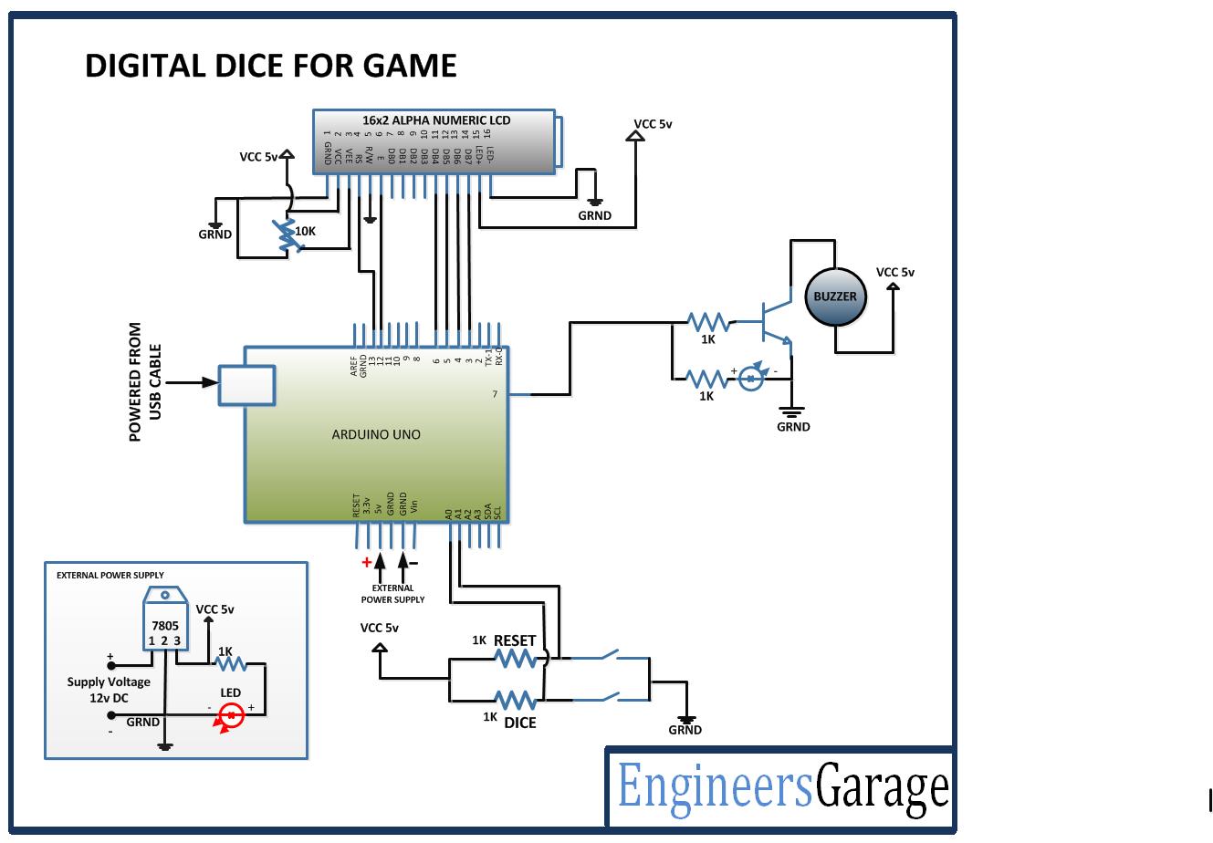
Fig. 1: Block Diagram of Arduino based Digital Dice
CIRCUIT CONNECTION
In the project, LCD display is controlled by the Arduino UNO. The Arduino board runs the project code to generate a random number and display it as a custom character on the LCD display. The circuit has the following sections- :
Power Supply – The Arduino UNO can be powered directly by the USB port of the board. The other components can be powered by connecting their ground and VCC pins with the common ground and VCC pins respectively. The Arduino UNO can also be powered by a DC power supply circuit. The entire circuit requires 5V DC supply that can be generated using 7805 voltage regulator. The power can be drawn from a regular battery which can be connected to the 7805 IC. The IC has three pins – pin 1 should be connected to the anode of the battery, pin 2 and 3 with the cathode (common ground). The 5V DC should be drawn from the pin 3 of the IC. An LED along with a 10K Ω pull-up resistor can also be connected between common ground and output pin to get a visual hint of supply continuity.
16X2 LCD – The 16X2 LCD display is connected to the Arduino board by connecting its data pins to pins 3 to 6 of the Arduino board. The RS and E pins of the LCD are connected to pins 13 and 12 of the Arduino UNO respectively. The RW pin of the LCD is grounded.

Fig. 2: Table listing circuit connections between Arduino Uno and Character LCD
The standard open-source library for interfacing LCD with Arduino UNO is used in the project. The library works as expected and needs no changes or modifications.
2-Switch Keypad – There are two tactile switches interfaced at A0 and A1 pins of the Arduino UNO. The pins by default are connected to VCC through 1K Ω pull up resistors receiving a HIGH logic. The switches are connected between ground and the pins. On pressing a switch, the respective pin is short-circuited to ground getting a LOW logic input. The switches have the following functions assigned to them.

Fig. 3: Table listing Arduino pins and respective functions in digital dice
Buzzer – A buzzer is connected at the pin 7 of Arduino UNO. The buzzer is connected through an NPN BC547 transistor circuit configured in common emitter configuration.
HOW THE PROJECT WORKS
The project is based on generating a random number between 0 and 7 and displaying the digit as a custom character on 16X2 LCD. The custom characters will be displayed using four character blocks of the LCD of which two character blocks will be on top row and other two character blocks will be in the bottom row adjacent to the blocks in top row. Each character block on 16X2 LCD is 5X8 pixels. The individual pixels of the character block can be switched ON or OFF by passing HIGH or LOW logic respective to those pixels to the LCD’s inbuilt controller. Any custom character can be displayed on a character block by switching individual pixels ON or OFF together. In this project four character blocks will be passed custom characters to form a single large-size character. The character blocks used for displaying a large custom character on LCD will be Column 0 Row 0, Column 1 Row 0, Column 0 Row 1 and Column 1 Row 1.
For displaying Zero (as default digit before dice trial), following pixel map will be assigned to the character blocks – :
Similarly, different pixel maps are assigned to the character blocks for displaying large custom characters for digits – 1, 2, 3, 4, 5 and 6.
When the project is powered on, it displays custom built zero “0” on the LCD. When trial switch is pressed, a random number between 0 and 7 is generated by the program code. Corresponding to the random number generated, predefined pixel maps are assigned to the four character blocks for displaying the respective large size custom character on LCD. If that number turns out to be “6”, the buzzer is started blowing to indicate that user gets an additional trial. The user can reset the LCD display to show large size zero again by pressing the Reset button.
PROGRAMMING GUIDE
The project will utilize standard open-source library of Arduino for LCD interfacing. So include LCD.h and define an object of LCD class. A constant for delay of 300 milliseconds is defined and variables to represent buzzer, dice button and reset button are defined and assigned to Arduino pins. A global variable to represent random number is declared.
To display zero, the pixel maps for Column 0 Row 0, Column 1 Row 0, Column 0 Row 1 and Column 1 Row 1 are defined as binary numbers in ZeroL, ZeroR, ZeroLB and ZeroRB arrays respectively.
To display one, the pixel maps for Column 0 Row 0, Column 1 Row 0, Column 0 Row 1 and Column 1 Row 1 are defined as binary numbers in OneL, OneR, OneLB and OneRB arrays respectively.
To display two, the pixel maps for Column 0 Row 0, Column 1 Row 0, Column 0 Row 1 and Column 1 Row 1 are defined as binary numbers in TwoL, TwoR, TwoLB and TwoRB arrays respectively.
To display three, the pixel maps for Column 0 Row 0, Column 1 Row 0, Column 0 Row 1 and Column 1 Row 1 are defined as binary numbers in ThreeL, ThreeR, ThreeLB and ThreeRB arrays respectively.
/*3*/
To display four, the pixel maps for Column 0 Row 0, Column 1 Row 0, Column 0 Row 1 and Column 1 Row 1 are defined as binary numbers in FourL, FourR, FourLB and FourRB arrays respectively.
To display five, the pixel maps for Column 0 Row 0, Column 1 Row 0, Column 0 Row 1 and Column 1 Row 1 are defined as binary numbers in FiveL, FiveR, FiveLB and FiveRB arrays respectively.
To display six, the pixel maps for Column 0 Row 0, Column 1 Row 0, Column 0 Row 1 and Column 1 Row 1 are defined as binary numbers in FiveL, FiveR, FiveLB and FiveRB arrays respectively.
A setup() function is called where the baud rate for serial transmission is set 9600 bits per second. The LCD is initialized using LCD.begin() function. The pinMode() function is used to set buzzer pin as output and button pins as digital input. Then, some initial messages are flashed on LCD screen.
A loop() function is called in which first the default character 0 is displayed on the LCD. The pressing of buttons is detected by detecting LOW logic at the pins. If Dice button is pressed, a random number between 0 and 7 is generated using random() function and assigned to “num” variable. If reset button is pressed, LCD display is cleared and “num” variable is assigned value 0. If the random number is 6 then a HIGH and LOW logic is passed to the buzzer pin for a delay of 100 milliseconds.
The value of “num” variable is checked through If-else statements and for value from 0 to 6, respective custom characters are created by assigning pixel map to character blocks using LCD.CreateChar() function. The parts of the large custom character are printed to the respective blocks by placing cursor at the respective character block and printing the character using lcd.write() function.
This ends the program code.
Project Source Code
###
#include <LiquidCrystal.h>// import the LCD library LiquidCrystal lcd(13, 12, 6, 5, 4, 3);// Pins used for RS,E,D4,D5,D6,D7 #define delayT 300 int BUZZ=7; //Digital pin 7 is used to ON relay 2 int DICE=A0; int RESET=A1; int a,b,c,num; byte zeroR[8] ={0b11100, 0b00110, 0b00011, 0b00011, 0b00011, 0b00011, 0b00011, 0b00011}; byte zeroL[8] ={0b00111, 0b01100, 0b11000, 0b11000, 0b11000, 0b11000, 0b11000, 0b11000}; byte zeroLB[8] ={0b11000, 0b11000, 0b11000, 0b11000, 0b11000, 0b11000, 0b01100, 0b00111}; byte zeroRB[8] ={0b00011, 0b00011, 0b00011, 0b00011, 0b00011, 0b00011, 0b00110, 0b11100}; /*1*/ byte oneL[8] ={0b00111, 0b01111, 0b11011, 0b00011, 0b00011, 0b00011, 0b00011, 0b00011}; byte oneLB[8] ={0b00011, 0b00011, 0b00011, 0b00011, 0b00011, 0b00011, 0b11111, 0b11111}; byte oneRB[8] ={0b10000, 0b10000, 0b10000, 0b10000, 0b10000, 0b10000, 0b11110, 0b11110}; byte oneR[8] ={0b10000, 0b10000, 0b10000, 0b10000, 0b10000, 0b10000, 0b10000, 0b10000}; /*2*/ byte twoL[8] ={0b00011, 0b00111, 0b01100, 0b01100, 0b01100, 0b01100, 0b00000, 0b00000}; byte twoR[8] ={0b11100, 0b01110, 0b00011, 0b00011, 0b00011, 0b00011, 0b00011, 0b00010}; byte twoRB[8] ={ 0b01110, 0b11100, 0b11000, 0b00000, 0b00000, 0b00000, 0b11111, 0b11111}; byte twoLB[8] ={0b00000, 0b00000, 0b00011, 0b00111, 0b01110, 0b11100, 0b11111, 0b11111}; /*3*/ byte threeL[8] ={0b00111, 0b01111, 0b00000, 0b00000, 0b00000, 0b00000, 0b00000, 0b00001}; byte threeR[8] ={0b11100, 0b01110, 0b00011, 0b00011, 0b00011, 0b00011, 0b00011, 0b11111}; byte threeRB[8] ={0b11111, 0b00011, 0b00011, 0b00011, 0b00011, 0b00011, 0b01110, 0b11100}; byte threeLB[8] ={0b00001, 0b00000, 0b00000, 0b00000, 0b00000, 0b00000, 0b00111, 0b01111}; /*4*/ byte fourL[8] ={0b11000, 0b11000, 0b11000, 0b11000, 0b11000, 0b11000, 0b11000, 0b11111}; byte fourR[8] ={0b00011, 0b00011, 0b00011, 0b00011, 0b00011, 0b00011, 0b00011, 0b11111}; byte fourRB[8] ={0b11111, 0b00011, 0b00011, 0b00011, 0b00011, 0b00011, 0b00011, 0b00011}; byte fourLB[8] ={0b11111, 0b00000, 0b00000, 0b00000, 0b00000, 0b00000, 0b00000, 0b00000}; /*5*/ byte fiveL[8] ={0b01110, 0b11110, 0b11000, 0b11000, 0b11000, 0b11000, 0b11000, 0b00111}; byte fiveR[8] ={0b11110, 0b11111, 0b00000, 0b00000, 0b00000, 0b00000, 0b00000, 0b11100}; byte fiveRB[8] ={ 0b11110, 0b00011, 0b00011, 0b00011, 0b00011, 0b00011, 0b11111, 0b11110}; byte fiveLB[8] ={ 0b00111, 0b00000, 0b00000, 0b00000, 0b00000, 0b00000, 0b01111, 0b00111}; /*6*/ byte sixL[8] ={ 0b01110, 0b11110, 0b11000, 0b11000, 0b11000, 0b11000, 0b11000, 0b11111}; byte sixR[8] ={0b11100, 0b11110, 0b00000, 0b00000, 0b00000, 0b00000, 0b00000, 0b11100}; byte sixRB[8] ={ 0b11110, 0b00011, 0b00011, 0b00011, 0b00011, 0b00011, 0b11111, 0b11110}; byte sixLB[8] ={ 0b11111, 0b11000, 0b11000, 0b11000, 0b11000, 0b11000, 0b01111, 0b00111}; void setup() { Serial.begin(9600); lcd.begin(16,2);//LCD 16x2 initialization pinMode(BUZZ, OUTPUT); pinMode(DICE, INPUT); pinMode(RESET, INPUT); lcd.setCursor(0,0); //Initially set the cursor position of LCD to 1st Columb 1st row. lcd.print("Engineers Garage");//After initialising print data lcd.setCursor(0,1); //Initially set the cursor position of LCD to 1st Columb 2nd row. lcd.print(" "); //print blank to clear all the data on LCD delay(3000); lcd.setCursor(2,0); lcd.print(" DIGITAL DICE "); } void loop() { lcd.setCursor(9,1); lcd.print(num); if(digitalRead(DICE) == 0){ num=random(0,7); delay(500); } if(digitalRead(RESET) == 0){ num=0; lcd.setCursor(0,0); lcd.print(" "); lcd.setCursor(0,1); lcd.print(" "); } if(num==6){ digitalWrite(BUZZ,1); delay(100); digitalWrite(BUZZ,0); delay(100); } if(num==0) { lcd.createChar(1,zeroR); lcd.createChar(2,zeroL); lcd.createChar(3,zeroRB); lcd.createChar(4,zeroLB); lcd.setCursor(1,0); lcd.write(1); lcd.setCursor(0,0); lcd.write(2); lcd.setCursor(1,1); lcd.write(3); lcd.setCursor(0,1); lcd.write(4); } if(num==1) { lcd.createChar(1,oneL); lcd.createChar(3,oneLB); lcd.createChar(2,oneR); lcd.createChar(4,oneRB); lcd.setCursor(0,0); lcd.write(1); lcd.setCursor(1,0); lcd.write(2); lcd.setCursor(0,1); lcd.write(3); lcd.setCursor(1,1); lcd.write(4); } if(num==2) { lcd.createChar(1,twoL); lcd.createChar(3,twoLB); lcd.createChar(2,twoR); lcd.createChar(4,twoRB); lcd.setCursor(0,0); lcd.write(1); lcd.setCursor(1,0); lcd.write(2); lcd.setCursor(0,1); lcd.write(3); lcd.setCursor(1,1); lcd.write(4); } if(num==3){ lcd.createChar(1,threeL); lcd.createChar(3,threeLB); lcd.createChar(2,threeR); lcd.createChar(4,threeRB); lcd.setCursor(0,0); lcd.write(1); lcd.setCursor(1,0); lcd.write(2); lcd.setCursor(0,1); lcd.write(3); lcd.setCursor(1,1); lcd.write(4); } if(num==4){ lcd.createChar(1,fourL); lcd.createChar(3,fourLB); lcd.createChar(2,fourR); lcd.createChar(4,fourRB); lcd.setCursor(0,0); lcd.write(1); lcd.setCursor(1,0); lcd.write(2); lcd.setCursor(0,1); lcd.write(3); lcd.setCursor(1,1); lcd.write(4);} if(num==5){ lcd.createChar(1,fiveL); lcd.createChar(3,fiveLB); lcd.createChar(2,fiveR); lcd.createChar(4,fiveRB); lcd.setCursor(0,0); lcd.write(1); lcd.setCursor(1,0); lcd.write(2); lcd.setCursor(0,1); lcd.write(3); lcd.setCursor(1,1); lcd.write(4);} if(num==6){ lcd.createChar(1,sixL); lcd.createChar(3,sixLB); lcd.createChar(2,sixR); lcd.createChar(4,sixRB); lcd.setCursor(0,0); lcd.write(1); lcd.setCursor(1,0); lcd.write(2); lcd.setCursor(0,1); lcd.write(3); lcd.setCursor(1,1); lcd.write(4); } }###
Circuit Diagrams
Project Video
Filed Under: Electronic Projects
Filed Under: Electronic Projects

Questions related to this article?
👉Ask and discuss on EDAboard.com and Electro-Tech-Online.com forums.
Tell Us What You Think!!
You must be logged in to post a comment.