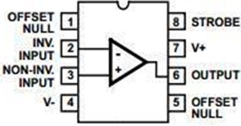
This Humidity detector circuit is based on two IC namely CA3130 and LM3914 and LED's to show you the stress meter with few more components.
IC CA3130 is operational amplifier which combines the advantage of both CMOS and bipolar transistor on a single chip. Operating voltage range varies from 5V to 16V. CA3130 has advantage that they can be phased compensated with a single external capacitor and have terminals for adjustment of offset voltage. In this you can adjust the reference voltage at inverting and non -inverting pin so that when voltage at inverting pin is more than non-inverting pin. It will make the out pin high and vice versa. Pin configuration of CA3130 IC is shown below.
LM3914 is a monolithic integrated circuit which senses the analog voltage and derives 10 LED's providing a linear analog display.
Advantage of IC LM3914-
1. In this user can easily select the dot or bar graph display just by changing a single pin.
2. This IC can drive LED's, LCD or vacuum fluorescent display.
3. You can cascade more IC's up to 100 steps.
4. This IC can also work on 3V power supply.
5. In this we do not require resistor with the LED's because current drive to LED's is regulated and programmed.
6. It will support wide temperature range from 0 degree to +70 degree Celsius.
Working of circuit
First of all we have to calibrate the circuit as different people have different moisture content in their hand so we have to adjust the bridge network made with the help of VR1 and R1. For this hold the electrodes in your hand normally and adjust VR1 so that only two or three LED glow. Now once you have set it no need to set it every time for same person.
Now your circuit is ready. Ask question to the person and if he is telling lie than some changes in body will take place and resistance of body decreases this will disbalance our bridge network build around VR1 and R1. And output of IC1 pin 6 will go high which is provided to pin 5 of IC2, LM3914 IC coverts the voltage into digital form and LED's start glowing. So according to input voltage at IC1, IC2 act and different number of LED's glow. Basically IC2 has internal stable voltage of 1.2V means after every 1.2V next LED will glow. You can change the reference voltage by varying the variable resistor VR2.
If you want the change the dot display to bar display just incorporate following changes-
1. For Bar graph display- Connect pin 9 directly to pin 3(supply voltage pin)
2. For dot display- Leave the pin 9 (mode selector pin) open.