Shown here is an easy to construct electronic circuit through which a motor can be made to run in both directions i.e. clockwise and anticlockwise. An interesting fact that adds to the curiosity of the circuit is that this is done by pressing a single switch. This project finds a good application in areas of robotics. The commonly used H-Bridge circuit uses two control signals to control both the directions of the motor. Before we begin explaining the circuitry, let’s have some information about the H-Bridge circuit.
H Bridge Circuit
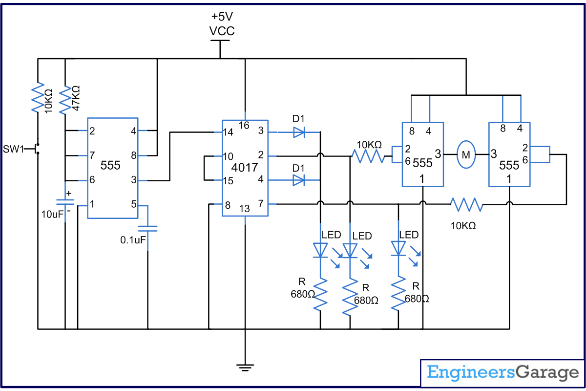
Mainly used to control DC motors and stepper motors, H-bridge divides the voltage on the either side of the load. In this circuit, two IC555 timers form the H-bridge circuit around the motor. These 555 timers work in astable mode. Lets find out more about how the circuit works.
The circuit of this project uses three 555 timer and one counter IC 4017. The IC1 (555) is used in monostable mode and the IC3 and IC4 are used in astable mode. The switch is connected to the trigger pin of IC1. Initially, when the switch in not pressed, there is no input to the trigger pin of the IC1 and hence no output is produced. The output of IC1 is used to provide clock pulse to IC2 (4017). Since there is no clock pulse the output Q0, which is at pin3 is high. The LED1 connected to it glows to indicate the off state. When the switch is pressed for the first time, IC1 gets trigger and a pulse is produced at the output pin 3 of IC1.
This pulse serves the purpose of clock for IC2. When the first clock pulse comes, the pin 2, which is output Q1 of the IC2, gets high. As a result the IC3 starts producing pulses which in turn drives the motor in one direction. The LED2 also glows to indicate the rotation of motor in one direction. When the second pulse comes, the output Q2 at pin gets high. The motor goes off and the LED1 will again glow to indicate the off state. With the next pulse the output Q3 will go high, thereby triggering the IC4 and motor starts to rotate in opposite direction. The LED 3 will glow to indicate the motor running in opposite direction. With the next pulse the output Q4 which is connected to reset pin goes high. This in turn will switch off the motor and make the system come to its initial stage.
Circuit Diagrams
Project Components
Filed Under: 555 Timers, Electronic Projects

Questions related to this article?
👉Ask and discuss on EDAboard.com and Electro-Tech-Online.com forums.
Tell Us What You Think!!
You must be logged in to post a comment.