Code lock described here is an electronic combination lock which can be used in daily life. The circuit is described here has following main advantages-
1 It is built using transistors and few more components; therefore small in size can be easily mounted on the doors.
2 This circuit also provides facility that when you press the wrong code it will disable the whole circuit for about 1 minute. Even if you enter the correct code than also lock will not open.
3 This circuit also provides you the facility to reset the circuit anytime when you need.
[[wysiwyg_imageupload:7843:]]
Fig. 1: Prototype Of Security Alarm with UM3561 IC On Breadboard
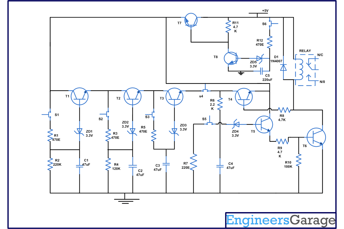
In this circuit we are using 6 switches. If switch S1 to S4 are pressed sequentially then lock will be opened. Switch S5 is the reset switch while switch S6 is used to disable the circuit. You can also increase the number of disable switches by connecting more switches in parallel with S6. One must take care while pressing the switch that “press time” should not be less than .75 second and not more than 1.25 seconds.
We have made switching circuit with the help of transistor T1 to T3, Zener diode (ZD1 to ZD3), Tactile switch (S1 to S3) and timing capacitor (C1 to C3). In this circuit, transistors T1-T3 are connected in series. When you press the push to on switches S1 to S4, timing capacitor C1, C2, C3 charges with the help of R1, R3, R5 respectively. Capacitor C1 discharges though resistor R2, ZD1 and T1, capacitor C2 discharge with the help of R4, ZD2, and T2. Similarly, capacitor C3 discharges through ZD3 and T3. During discharge, we have used different values of resistor like for C1, R2 (220K), For C2, R4 (120K). That’s why discharge timing of capacitor differs, for instance, for C1 it is 6 seconds, 3 seconds for C2 and 1.5 seconds for C3. Therefore while activating the switch one must take care of this timing.
When the correct sequence of switches (S1-S4) is pressed, capacitor C4 charges through R6. This makes transistors T4, T5, T6 to start conducting and relay connected to them becomes energized. If you want to reset the circuit, press S5, it will discharge the capacitor C4 through ZD4 and R7.
When switch S6 is pressed, capacitor C5 starts charging through R12 and because of that transistor T8 starts conducting with the help of ZD5. In this case, collector voltage of transistor T8 becomes low. Therefore transistor T7 stop a conducting thus cutting off the positive supply to switches (S1-S5) and transistor (T1-T3). Now, capacitor C5 takes almost 1 minute to discharge making the circuit locked for the next 1 minute and the relay connected to it will not energize. (Also check electronic code lock project using 8051 microcontroller)
Circuit Diagrams
Project Components
Project Video
Filed Under: Electronic Projects
Filed Under: Electronic Projects


Questions related to this article?
👉Ask and discuss on EDAboard.com and Electro-Tech-Online.com forums.
Tell Us What You Think!!
You must be logged in to post a comment.