Mine workers have a harsh job. They have to work deep down the earth. At such depths, they are almost disconnected from the everything and everyone. Even the mobile network does not work at those depths. The loss of connectivity leads to delay in any help in case of a danger or underground mishap. This project is built to detect any danger in advance and relay alert among the mine workers. Though most wireless networks don’t work underground, small-distance radio communication can be used in such situation.
The project uses a gas sensor, temperature and humidity sensor and light sensor to detect any sign of danger. The data from the sensors is sent to a computer through radio communication for continuous monitoring. The data acquired from the sensors is continuously logged in an excel sheet and if sensor data exceeds pre-determined values, a buzzer is activated to alert the mine workers. As a demonstration of radio communication, 434 MHZ RF module is used in the project. The module can transmit data over a distance of 50-60 meter typically and with the use of an antenna and proper transmission power, it can transmit data over 300 to 350 meter distance. On building actual emergency system from the prototype, other advanced radio communication module can be used.

Fig. 1: Prototype of Transmitter Circuit of Emergency System for Mine Workers
This prototype model of the emergency system for mines is built on Arduino boards. The wearable gadget having interfaced sensors is built on Arduino Pro Mini and the receiver device fetching sensor data and connected to a computer for data logging is built on Arduino Mega. The Arduino sketch for both the devices is written using Arduino IDE and burnt to the boards using AVR Dude.
Components Required
Wearable Gadget –
1. Arduino UNO
2. 7805 voltage regulator
3. Tx RF 433MHz module.
4. 1K ohm resistor -4 pcs
5. 5mm LED
6. MQ-6 gas sensor
7. DTH11 sensor
8. LDR
Receiver Device –
1. Arduino MEGA
2. Rx RF 433MHz module.
3. 1K ohm resistor
4. 5mm LED
5. BC547 transistor
6. 5v Buzzer
Block Diagram –

Fig. 2: Block Diagram of Emergency System for Mine Workers
Circuit Connections –
The receiver device is built on the Arduino Mega. The Arduino board is interfaced with a RF receiver to fetch data from the wearable gadgets, a computer for data logging and a buzzer circuit. The different components are interfaced to the Arduino board in the following manner –
RF Receiver – The receiver module is directly interfaced with the Arduino board. The RF receiver module has 8 pins and has following pin configuration –

Fig. 3: Table listing pin configuration of RF Receiver
The carrier wave from the antenna is received at the pin 8 of the module. The extracted data in serial form is output at pin 2 of the module. The pin 2 of the module is connected to pin 11 of the Arduino Mega and VCC and Ground pins of the module are connected to the common VCC and Ground. An antenna of quarter wavelength height is connected at pin 8 of the module for range extension.
Computer – The Arduino board is connected to the computer through USB cable. On the desktop system, PLX-DAQ application need to be run. The user needs to download the PLX-DAQ application from the parallax.com. On installing the application, a folder with same name will be created on the desktop window. Open the file PLX-DAQ Spreadsheet in the folder PLX-DAQ and on opening the file a security warning will pop up.

Fig. 4: Screenshot of PLX-DAQ Spreadsheet
Select “Enable this content” on the alert box and click Okay.

Fig. 5: Screenshot of Alert Box in PLX-DAQ Spreadsheet
A message showing that application is about to initialize ActiveX controls will pop up. Click the OK button to enable ActiveX controls.
A window prompting to configure COM port for serial communication will pop up. Select the COM port according to the connection and set the baud rate 9600 bits per second. Tap the “Connect” button to start data acquisition. The receiver device will wait for availability of the data and there is sensor data available, it will start logging it on the excel sheet.
The desktop computer communicates with the Arduino board over virtual serial communication.
Buzzer – A buzzer is interfaced to the Arduino board to generate alarm. The buzzer is connected at pin A7 of the Arduino through a switching transistor circuit. The base of the transistor is connected t the Arduino pin through 1K ohms resistor. The emitter pin of the transistor is grounded while collector pin is connected to the buzzer. The other terminal of the buzzer is connected to VCC. An LED with 1K ohms series resistor is connected parallel to the buzzer circuit for visual hint of the alert.
Power supply – The power is provided by a 18V battery. The supply from the battery is regulated to 5V DC using 7805 voltage regulator IC. The IC has three pins – pin 1 should be connected to anode of the battery, pin 2 and 3 with the cathode (common ground). The 5V DC should be drawn from the pin 3 of the IC. An LED along with a 10K Ω pull-up resistor can also be connected between common ground and output pin to get a visual hint of supply continuity.
The wearable gadget to be used by the mine workers is built on Arduino Pro Mini. Many gadgets can be provided to the mine workers. The gadget has RF Transmitter, DHT11 temperature and humidity sensor, MQ6 gas sensor and LDR sensor interfaced with the Arduino board. The sensors and RF module are interfaced to the Arduino board in the following manner –
DHT11 Temperature and Humidity Sensor – This is a digital sensor with inbuilt capacitive humidity sensor and Thermistor. It relays a real-time temperature and humidity reading every 2 seconds as a digital output. The pin 1 and 4 of DHT11 are VCC and Ground respectively. The output is received from pin 2 of the sensor which is feed to pin A0 of the Arduino board through a 10K ohm pull up resistor.
MQ6 Gas Sensor – The MQ6 gas sensor is a gas sensor module. The module has 4 pins for interfacing of which two pins are VCC and ground, one pin is analog output and one pin is digital output pin. The analog output pin of the module is used for detecting concentration level of gas leakage and interfaced with the A1 analog input pin of the Arduino board. The sensor measures the concentration of leaked gas in ppm according to the following formulae –
Concen = 1036.5*R^-2.392 Where
Concen is the concentration of LPG in ppm
R is the ratio of Rs the resistance of sensor to the R0 which is the resistance at 1000ppm at 20 degree Celsius and 65% humidity
The resistance of the sensor Rs is given by the formulae –
Rs = (1024/ADC_DATA-1)*RL where
Rs is the resistance of the sensor
ADC_DATA is digital reading ranging from 0 to 1023
RL is load resistance ranging from 10K to 40K ohms
Therefore, for a fixed load resistance, the ADC reading is proportional to the concentration of gas in ppm.
In the datasheet the ratio of concentration to the sensor resistance is given. The graph is done under the normal condition of 20 degree Celsius and 65% humidity. And that means Rs=R0 for the curve.

Fig. 6: Graph showing sensitivity curve of MQ-6 Sensor
This way the concentration of gas in ppm becomes equal to ADC reading. The ADC reading ranges between 0 and 1023.
LDR Sensor – The LDR is used to sense the intensity of light. The sensor is connected to the A2 pin of Arduino board. The sensor is connected in a potential divider circuit. The LDR provides an analog voltage which is converted to digital reading by the in-built ADC.
RF Transmitter – The RF transmitter sends the sensor data to the receiver device. The module has the following pin configuration –

Fig. 7: Table listing pin configuration of RF Transmitter
The VCC and ground of the module are connected to the common VCC and ground. An antenna is connected at pin 4 and pin 2 of the module is connected to the pin 11 of the Arduino Pro Mini.
Power supply – The gadgets also have similar power supply circuit as the receiver device. The power is provided by a 18V battery. The supply from the battery is regulated to 5V DC using 7805 voltage regulator IC.
How the circuit works –

Fig. 8: Prototype of Receiver Circuit of Emergency System for Mine Workers
The receiver device and the wearable gadgets are connected through the RF module. When the gadget is powered on, the Arduino board loads the libraries for different sensors and read sensor data in the form of analog voltage from the LDR and MQ6 gas sensor and digital data from the DHT 11 temperature and humidity sensor. The sensor readings are formatted in strings and passed serially to the RF transmitter for radio transmission.
The receiver device detects the RF data with the help of RF receiver. The RF receiver passes the strings containing sensor data serially to the Arduino Mega. The Arduino board send the sensor data to computer on virtual serial port and compare the read sensor values with threshold values. If value from any sensor exceeds the threshold value, the Arduino sends a HIGH logic at the pin connecting buzzer invoking an alarm.
Check out the gadget code to learn how the Arduino board reads sensor data available in analog and digital form and transfer it to RF module. Check out the receiver device code to learn how sensor data is read from the RF receiver, sent to the computer and compared for activating alarm.
Programming Guide –
Wearable Gadget Code
First the standard libraries for RF communication and handling DHT sensor are imported. It is assumed that an LED is connected at pin 13 of the board for indication of data transmission for which a variable is declared. The variables to hold four sensor values are declared and string variables to hold string representations of the sensor values are declared.
The setup() function is called in which the LED pin is set digital output and virtual serial port is enabled by calling vw_set_ptt_inverted() function. The pin 12 is assigned for virtual serial transmission where the data pin of RF transmitter is connected. The baud rate for serial transmission is set to 4000 KBPS by using function vw_setup();

Fig. 9: Screenshot of Initialization in Arduino Code for Transmitter Circuit of Emergency System for Mine Workers
The data from the LDR sensor is read in Sensor1Data0, humidity value from DHT 11 sensor is read in Sensor1Data1, temperature value from DHT 11 sensor is read in Sensor1Data2 and gas concentration in Sensor1Data3 variables. The integer values are converted to string and stored in string type variables. The strings are concatenated in a single variables and converted to an array. The array is passed for serial transmission. The data available for serial transmission is sent on the virtual serial port using vw_send() function and Arduino is forced to wait till all elements of the array are transmitted.

Fig. 10: Screenshot of Loop Function in Arduino Code for Transmitter Circuit of Emergency System for Mine Workers
This completes the gadget side code.
Receiver Device Code
On the receiver device, the Arduino loads the VirtualWire library for handling RF data. It is assumed that an LED is connected at pin 13 of the board for indication of data reception for which a variable is declared. A variable is declared to represent buzzer and variables to hold string message and some variables are declared.
The setup() function is called in which baud rate for serial communication with the computer is set to 9600 bits per second and some initial messages are sent to the computer for printing. The pins connecting buzzer and LED are set digital output. The RF communication is enabled by calling vw_set_ptt_inverted() function and baud rate for RF communication is set to 4000 KBPS using vw_setup() function. The reception of RF data is started by calling vw_rx_start() function.

Fig. 11: Screenshot of Initialization in Arduino Code for Receiver Circuit of Emergency System for Mine Workers
The loop() function is called in which the received string carrying sensor data is read and stored in array. The array elements are passed to the computer for printing on the XML sheet. The values of the array are compared with threshold values and if either of the sensor’s value exceeds the threshold value, the buzzer is activated.

Fig. 12: Screenshot of Loop Function in Arduino Code for Receiver Circuit of Emergency System for Mine Workers
Fig. 13: Screenshot of Loop Function in Arduino Code for Receiver Circuit of Emergency System for Mine Workers
This completes the receiver device code for Emergency System of Mine Workers.
Project Source Code
###
#include <VirtualWire.h> #include<dht.h> // LED's const int ledPin = 13; dht DHT; #define dht_dpin A1 // Sensors int Sensor1Data0,Sensor1Data1,Sensor1Data2; char Sensor1CharMsg[10];//,Sensor1CharMsg0[6],Sensor1CharMsg1[6],Sensor1CharMsg2[6]; String str,str0,str1,str2; void setup() { pinMode(13,OUTPUT); vw_set_ptt_inverted(true); // vw_set_tx_pin(12); vw_setup(4000);// speed of data transfer Kbps } void loop(){ // Read and store Sensor 1 data DHT.read11(dht_dpin); Sensor1Data0 = analogRead(A0); Sensor1Data1 = DHT.humidity;//analogRead(A1); Sensor1Data2 = DHT.temperature; // Convert integer data to Char array directly str0=String(Sensor1Data0); str1=String(Sensor1Data1); str2=String(Sensor1Data2); //Sensor1CharMsg=Sensor1CharMsg0+Sensor1CharMsg1+Sensor1CharMsg2; //DEBUG str='A'+str0+str1+str2; str.toCharArray(Sensor1CharMsg, 10); Serial.print("Sensor1 Integer: "); Serial.print(Sensor1Data0); Serial.print(" Sensor1 CharMsg: "); Serial.print(Sensor1CharMsg); Serial.println(" "); delay(1000); digitalWrite(13, true); // Turn on a light to show transmitting vw_send((uint8_t *)Sensor1CharMsg, strlen(Sensor1CharMsg)); vw_wait_tx(); // Wait until the whole message is gone digitalWrite(13, false); // Turn off a light after transmission delay(200); } // END void loop... #include <VirtualWire.h> #include<dht.h> // LED's const int ledPin = 13; dht DHT; #define dht_dpin A1 // Sensors int Sensor1Data0,Sensor1Data1,Sensor1Data2; char Sensor1CharMsg[10];//,Sensor1CharMsg0[6],Sensor1CharMsg1[6],Sensor1CharMsg2[6]; String str,str0,str1,str2; void setup() { pinMode(13,OUTPUT); vw_set_ptt_inverted(true); // vw_set_tx_pin(12); vw_setup(4000);// speed of data transfer Kbps } void loop(){ // Read and store Sensor 1 data DHT.read11(dht_dpin); Sensor1Data0 = analogRead(A0); Sensor1Data1 = DHT.humidity;//analogRead(A1); Sensor1Data2 = DHT.temperature; // Convert integer data to Char array directly str0=String(Sensor1Data0); str1=String(Sensor1Data1); str2=String(Sensor1Data2); //Sensor1CharMsg=Sensor1CharMsg0+Sensor1CharMsg1+Sensor1CharMsg2; //DEBUG str='B'+str0+str1+str2; str.toCharArray(Sensor1CharMsg, 10); Serial.print("Sensor1 Integer: "); Serial.print(Sensor1Data0); Serial.print(" Sensor1 CharMsg: "); Serial.print(Sensor1CharMsg); Serial.println(" "); delay(1000); digitalWrite(13, true); // Turn on a light to show transmitting vw_send((uint8_t *)Sensor1CharMsg, strlen(Sensor1CharMsg)); vw_wait_tx(); // Wait until the whole message is gone digitalWrite(13, false); // Turn off a light after transmission delay(200); } // END void loop...###
Circuit Diagrams
| Circuit-Diagram-Data-Acquisition-System-Mine-Worker | 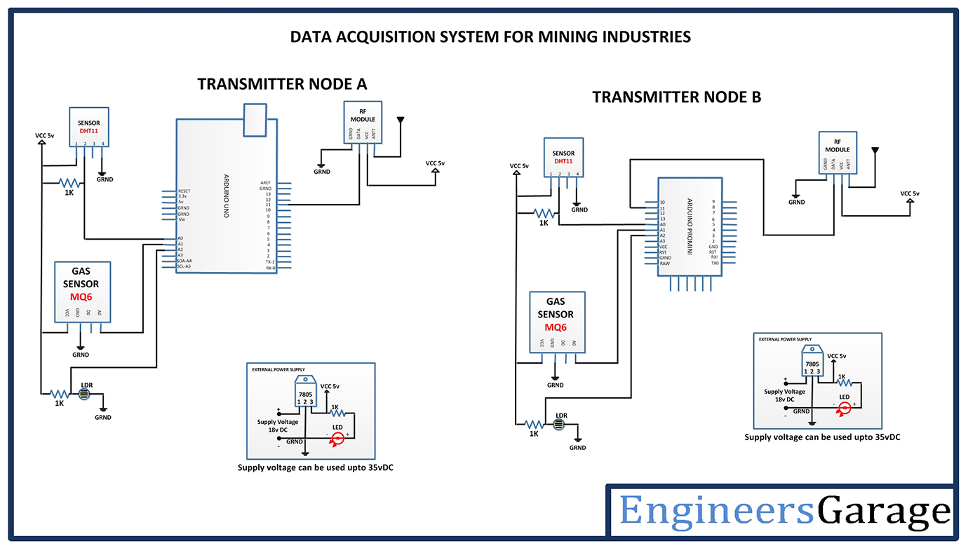 |
| Circuit-Diagram-Receiver-Data-Acquisition-System-Mine-Worker |  |
Project Video
Filed Under: Electronic Projects
Filed Under: Electronic Projects

Questions related to this article?
👉Ask and discuss on Electro-Tech-Online.com and EDAboard.com forums.
Tell Us What You Think!!
You must be logged in to post a comment.