GPS is a common device which is used in many electronics applications like Vehicle Tracking System, Soldier Tracking System, Traffic Navigation and Surveillance System and many other systems. The main aim of the project is to get accurate times while using GPS Clock. GPS clock is a Universal Clock Which is mostly used at Railways Stations, Bus Stands and Airports. It is widely used for Military purposes too. In this project we are using Arduino pro mini for GPS updated clock… Arduino pro mini is an ATmega168 based microcontroller board, which is small in size and can be fitted on bread board easily.

Fig. 1: Prototype of Arduino based GPS Clock
Here we have tried to extract GPS time and date from a string that comes from GPS. The name of this string is $GPRMC, the length of this string is about 70 characters.

Fig. 2: Block Diagram of Arduino based GPS Clock
In the above block diagram, we can see the process of the whole system. In this block diagram Arduino takes GPS output and after extracting time and date, send the same to the 16×2 LCD.
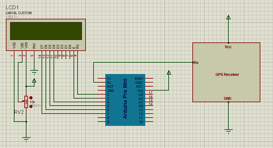
GPS updated time is displayed on 16×2 LCD. The Data pins of 16×2 LCD is directly connected with Arduino in 4-bit mode. GPS’s Tx pin is connected with Rx pin of the Arduino.
Circuit
In the circuit which you can find on the circuit diagram tab shows that an Arduino pro mini is used which controls all the process or receives GPS’s output. After having received the GPS output, Arduino reads all the string and stores required string in a string or in an array. After storing the required string, Arduino extracts the time and date from the stored string and then sends it to the 16×2 LCD. Here 16×2 LCD is used for displaying time and date. The data pins d5, d6, d7, d8 of 16×2 LCD are directly connected with pin no. 4, 5 , 6, 7 of Arduino respectively and command pin Rs and En of 16×2 LCD is also directly connected with pin 2 and 3 of Arduino respectively. GPS receiver’s Tx pin is directly connects with Rx pin of Arduino. The most important thing is ground of Arduino and GPS should be connected with each other. Here GPS module is operated on 4800 bps baud rate. The Arduino is configured at 4800 bps baud rate by using class “Serial.begin(4800)”.
GPS Output

Fig. 3: Screenshot of Arduino Serial Port showing GPS data
In the above image the output of GPS receiver is shown. In this window we can see many strings but we have to use only $GPRMC in which after first comma we can see time in 24-Hour format and after the nine commas we can see date. By using Arduino these date and time are extracted from this $GPRMC string and stores time in a string and date also stores in another string and after this process displays both the date and time on LCD.
Components Used
· Arduino
· GPS
· 16×2 LCD
· Connecting wires
· Power supply
Project Source Code
###
#include<LiquidCrystal.h> LiquidCrystal lcd(2, 3, 4, 5, 6, 7); char str[70]; char *test="$GPRMC"; char time[6]; char date[6]; int temp,i; void setup() { lcd.begin(16,2); Serial.begin(4800); lcd.setCursor(0,0); lcd.print("GPS Update Clock"); lcd.setCursor(0,1); lcd.print(" By Saddam Khan "); delay(3000); } void loop() { int j=0,k=0; //temp=1; if (temp==1) { for(int i=7;i<13;i++) //extract latitude from string { time[j]=str[i]; j++; } for(int i=57;i<63;i++) { date[k]=str[i]; k++; } lcd.clear(); lcd.setCursor(0,0); //display latitude and longitude on 16X2 lcd display lcd.print("Date: "); for(int i=0;i<2;i++) lcd.print(date[i]); lcd.print("/"); for(int i=2;i<4;i++) lcd.print(date[i]); lcd.print("/"); for(int i=4;i<6;i++) lcd.print(date[i]); lcd.setCursor(0,1); lcd.print("Time: "); for(int i=0;i<2;i++) lcd.print(time[i]); lcd.print(":"); for(int i=2;i<4;i++) lcd.print(time[i]); lcd.print(":"); for(int i=4;i<6;i++) lcd.print(time[i]); delay(100); temp=0; j=0; i=0; k=0; } } void serialEvent() { while (Serial.available()) //Serial incomming data from GPS { char inChar = (char)Serial.read(); str[i]= inChar; //store incomming data from GPS to temparary string str[] i++; // lcd.print(inChar); if (i < 7) { if(str[i-1] != test[i-1]) //check for right string { i=0; } } if(i >=65) { temp=1; } } }###
Circuit Diagrams
Project Video
Filed Under: Electronic Projects
Filed Under: Electronic Projects

Questions related to this article?
👉Ask and discuss on Electro-Tech-Online.com and EDAboard.com forums.
Tell Us What You Think!!
You must be logged in to post a comment.