What are waves?
An electronic circuit used to generate a continuous output signal usually in the form of a sinusoid at some predetermined frequency or wavelength set by the resonant components of the circuit.
Types of wave
{C}{C} 1.Uni-directional Waveforms – these waveforms are always positive or negative in nature flowing in one forward direction only as they do not cross the zero axis point. Common uni-directional waveforms include Square-wave timing signals, Clock pulses and Trigger pulses.
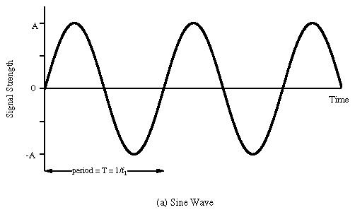
{C}{C} 2.Bi-directional Waveforms – these waveforms are also called alternating waveforms as they alternate from a positive direction to a negative direction constantly crossing the zero axis point. Bi-directional waveforms go through periodic changes in amplitude, with the most common by far being the Sine-wave.
What is frequency?
Frequency is the number of occurrences of a repeating event per unit time. It is also referred to as temporal frequency, which emphasizes the contrast to spatial frequency and angular frequency.
Types of Waveforms
{C}{C} 1. Sine Wave Waveform
{C}{C} 2. Square Wave Waveforms

{C}{C} 3. Rectangular Waveforms

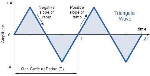
{C}{C} 4. Triangular Waveforms
{C}{C} 5. Saw tooth Waveforms

How to generate Wave?
Wave is a signal that cannot be made by any simple device. It requires a capacitor and resistor combination that helps in the charging and discharging of the capacitor and makes that type of wave.
There is a device called 8038 which generate any type of the waves.
ICL8038 waveform generator
The 8038 waveform generator is an Integrated circuit by Intersil designed to generate accuracy sine, square & triangular waveforms based on bipolar monolithic technology involving Schottky barrier diodes. Triangular waves were produced by charging and discharging a capacitor with constant currents. The triangular waves were converted to sine waves involving a non-linear network of transistors and thin-film resistors.
The output frequency was set by resistors or capacitors and covered a range from 0.001 Hz to more than 300 kHz. An external control voltage would accomplish frequency sweeping or frequency modulation. The temperature drift could be optimized to less than 250ppm/°C by combining it with a PLL.
Maxim designed a copy of the ICL8038 and marketed it as MAX038. Both devices were meanwhile discontinued.
Pinout:


Test Circuit:

Calculation:
The symmetry of all waveforms can be adjusted with the external timing resistors. Two possible ways to accomplish this are shown in Figure 3. Best results are obtained by keeping the timing resistors RA and RB separate (A). RA controls the rising portion of the triangle and sine wave and the 1 state of the square wave.
The falling portion of the triangle and sine wave and the 0 state of the square wave is:

Thus a 50% duty cycle is achieved when RA = RB. If the duty cycle is to be varied over a small range about 50% only, the connection shown in Figure 3B is slightly more convenient. A 1k? potentiometer may not allow the duty cycle to be adjusted through 50% on all devices. If a 50% duty cycle is required, a 2k? or 5k? potentiometer should be used.
With two separate timing resistors, the frequency is given by:
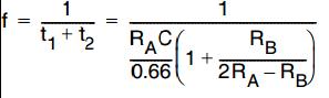
Or, if RA = RB = R

Selecting RA, RB and C
Selecting RA, RB and C:
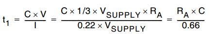
For any given output frequency, there is a wide range of RC combinations that will work, however certain constraints are placed upon the magnitude of the charging current for optimum performance. At the low end, currents of less than 1?A are undesirable because circuit leakages will contribute significant errors at high temperatures. At higher currents (I > 5mA), transistor betas and saturation voltages will contribute increasingly larger errors. Optimum performance will, therefore, be obtained with charging currents of 10?A to 1mA. If pins 7 and 8 are shorted together, the magnitude of the charging current due to RA can be calculated from

R1 and R2 are shown in the Detailed Schematic.
A similar calculation holds for RB.
The capacitor value should be chosen at the upper end of its possible range.
Waveform out Level Control and Power Supplies:
The waveform generator can be operated either from a single power supply (10V to 30V) or a dual power supply (±5V to ±15V). With a single power supply the average levels of the triangle and sine wave are at exactly one-half of the supply voltage, while the square wave alternates between V+ and ground. A split power supply has the advantage that all waveforms move symmetrically about ground.
The square wave output is not committed. A load resistor can be connected to a different power supply, as long as the applied voltage remains within the breakdown capability of the waveform generator (30V). In this way, the square wave output can be made TTL compatible (load resistor connected to +5V) while the waveform generator itself is powered from a much higher voltage.
Frequency Modulation and Sweeping:
The frequency of the waveform generator is a direct function of the DC voltage at Terminal 8 (measured from V+). By altering this voltage, frequency modulation is performed. For small deviations (e.g. ±10%) the modulating signal can be applied directly to pin 8, merely providing DC decoupling with a capacitor as shown in Figure 5A. An external resistor between pins 7 and 8 is not necessary, but it can be used to increase input impedance from about 8k? (pins 7 and 8 connected together), to about (R + 8k?).
For larger FM deviations or for frequency sweeping, the modulating signal is applied between the positive supply voltage and pin 8 (Figure 5B). In this way the entire bias for the current sources is created by the modulating signal, and a very large (e.g. 1000:1) sweep range is created (f = Minimum at VSWEEP = 0, i.e., Pin 8 = V+). Care must be taken, however, to regulate the supply voltage; in this configuration the charge current is no longer a function of the supply voltage (yet the trigger thresholds still are) and thus the frequency becomes dependent on the supply voltage. The potential on Pin 8 may be swept down from V+ by (1/3 VSUPPLY – 2V).

TI Innovation Challenge
Texas Instruments Innovation Challenge 2014
Innovate using Texas Instruments Analog ICs and Embedded Processors!
Take part in the Texas Instruments Innovation Challenge: India Analog Design Contest 2014 and win up to US$ 17,000.
What is the Contest a
Project Source Code
Filed Under: Electronic Projects

Questions related to this article?
👉Ask and discuss on EDAboard.com and Electro-Tech-Online.com forums.
Tell Us What You Think!!
You must be logged in to post a comment.