In present times there are many types of Home Automation Systems which are available in the market. Most of these are simple Home Appliances Controlling Systems like DTMF controlled Home Appliances, GSM based Home Appliances Controlling, RF based Home Appliances Controlling. Here we are going to discuss about TV or DVD Remote Control LED Home / Office Appliances Control (Home Automation System) using Arduino Board.
In this project, TSOP (IR Receiver) is connected with Arduino. Arduino receives encoded signal coming from IR Remote and then decodes by using IRremote.h library, which is easily available on internet (Find this library by typing on Google IR remote library for Arduino). After decoding the signal, compare decoded signal with defined value, if the match occurs then perform related function or switching on/off related relay by using digital input/output. Here AC load is used for demonstration. Three Home/Office Appliances are used for demonstration. In which one zero watt bulb indicated by light 1 and second is 100 watt bulb indicated by light 2 and third and last is TV/LCD indicated by TV. LCD is also interfaced with arduino in this system for displaying the current status of Appliances like TV ON, TV OFF, light 1 ON, light 1 OFF, light 2 ON, light 2 OFF, ALL ON, ALL OFF etc.

Fig. 1: Image showing IR Remote used for controlling Home Automation System

Fig. 2: Prototype of Arduino based IR Remote controlled Home Automation System

Fig. 3: Image showing switching a bulb on by IR Remote via Home Automation System

Fig. 4: Image showing display panel in prototype of Arduino based Home Automation System
Fig. 5: Image showing Relay Circuit used in Arduino based Home Automation System

Fig. 6: Image of Display Panel of Home Automation System showing switching status of a home appliance

Fig. 7: Image of LED TV controlled by Arduino based Home Automation System

Fig. 8: Image showing circuit connections of Arduino based Home Automation System with an LED TV
Block Diagram

Fig. 9: Block Diagram of Arduino based IR Remote controlled Home Automation System
Circuit Description
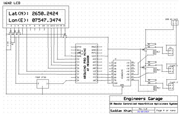
It is assumed that the reader has gone through the project how to get started with the arduino and done all the things discussed in it. Circuit of this system is very simple in this TSOP 1738 connected to digital pin 9 of Arduino, which detects 38 KHz IR frequency and relays are connected to digital pin 10, 11, 12 of Arduino for controlling light 1, light 2, TV respectively using ULN 2003 IC is a high-voltage high-current Darlington transistor arrays. Each consists of seven NPN Darlington pairs that feature high-voltage outputs with common-cathode clamp diodes for switching inductive loads and 5 volt relays are used here, which are best suitable for these types of Projects. Light 1 is connected with relay 1, light 2 is connected with relay 2 and TV is connected with relay 3.

Fig. 10: Circuit Diagram of TSOP1738 based IR Receiver
Relay Connection Circuit for DC supply (connect AC supply in place of battery and electrical appliances in place of LED polarity does not effects in AC.)
You can add more Home/Office Appliances with this system by adding some functions in the program. 16×2 LCD’s commands pins RS and EN is directly connected with pin 7 and 6 respectively and Data pins d4, d5, d6, d7 are connected with 5, 4, 3, 2 pins of Arduino.
Working & Components Used
Working
1. When we press key 1, this is responsible for tuning on TV/LCD and if we again press this, key is now responsible for tuning off TV.
2. When we press key 2 this is responsible for tuning on light 1 and if we again press this key it is now light 1 tuned off.
3. When we press key 3 this is responsible for tuning on light 2 and if we again press this key it is now light 2 tuned off.
Programming
Programming of this project is very easy. Initialize IR Remote library and LCD library. Then define some strings for match or compare. Store IR decoded result and compare this with defined strings. If any match occurs perform related function then enjoy it.
Components Used
2. TSOP 1738
3. Connecting wires
4. Power supply
5. AC appliances
6. Resisters
7. Capacitors
8. IR remote
9. Relays
10. ULN2003
Project Source Code
###
#include<LiquidCrystal.h> #include <IRremote.h> int RECV_PIN = 9; // Output pin of TSOP sensor IRrecv irrecv(RECV_PIN); decode_results results; LiquidCrystal lcd(7,6,5,4,3,2); #define light1 10 #define light2 11 #define TV 12 int temp=0,temp1; void setup() { lcd.begin(16,2); pinMode(light1,OUTPUT); pinMode(light2,OUTPUT); pinMode(TV,OUTPUT); pinMode(13,OUTPUT); lcd.setCursor(0,0); lcd.print(" Home/Office "); lcd.setCursor(0,1); lcd.print(" Aplliances ctrl"); delay(2000); lcd.setCursor(0,0); lcd.print("Using IR Remote "); lcd.setCursor(0,1); lcd.print("By Saddam Khan "); delay(2000); lcd.clear(); lcd.setCursor(0,0); lcd.print("Engineers Garage"); delay(2000); irrecv.enableIRIn(); // Start the receiver } void loop() { int i,j,k,l,m; lcd.clear(); while(1) { lcd.setCursor(0,1); lcd.print("System Ready "); delay(100); if (irrecv.decode(&results)) { digitalWrite(13, HIGH); delay(10); digitalWrite(13, LOW); if((results.value)== 33441975) // on off red button { if(i%2==0) { digitalWrite(TV, LOW); digitalWrite(light2, LOW); digitalWrite(light1, LOW); lcd.clear(); lcd.setCursor(0,0); lcd.print("ALL OFF "); delay(10); } else { digitalWrite(TV, HIGH); digitalWrite(light2, HIGH); digitalWrite(light1, HIGH); lcd.clear(); lcd.setCursor(0,0); lcd.print("ALL ON "); delay(100); } i++; } if((results.value)== 33444015) // key 1 { if(j%2==0) { digitalWrite(TV, HIGH); lcd.clear(); lcd.setCursor(0,0); lcd.print("TV ON"); delay(10); } else { digitalWrite(TV, LOW); lcd.clear(); lcd.setCursor(0,0); lcd.print("TV OFF"); delay(10); } j++; } if((results.value)== 33478695) // key 2 { if(k%2==0) { digitalWrite(light1, HIGH); lcd.clear(); lcd.setCursor(0,0); lcd.print("LIGHT 1 ON"); delay(10); } else { digitalWrite(light1, LOW); lcd.clear(); lcd.setCursor(0,0); lcd.print("LIGHT 1 OFF"); delay(10); } k++; } if((results.value)== 33486855) // key 3 { if(l%2==0) { digitalWrite(light2, HIGH); lcd.clear(); lcd.setCursor(0,0); lcd.print("LIGHT 2 ON"); delay(10); } else { digitalWrite(light2, LOW); lcd.clear(); lcd.setCursor(0,0); lcd.print("LIGHT 2 OFF"); delay(10); } l++; } irrecv.resume(); // Receive the next value } } }###
Circuit Diagrams
Project Video
Filed Under: Electronic Projects
Filed Under: Electronic Projects

Questions related to this article?
👉Ask and discuss on EDAboard.com and Electro-Tech-Online.com forums.
Tell Us What You Think!!
You must be logged in to post a comment.