While driving car, Before taking a turn it is a good practise to use the indicator, which will not only alert the other vehicle driver nearby you but reduces the chances of accident as well. But if your vehicle indicator is not working well then you can use this simple circuit. In night many accident took place because of less traffic, high speed and casual driving.
We forget to use indicator and speeding vehicle behind you or from opposite side does not get time to slow or stop their vehicle. Therefore the use of indicator is always required in driving and while turning. This small circuit can also be used for two wheeler even in bicycle. Main advantage of this circuit is, it will not only give a visual indicator but also give you a buzzer sound while turning left or right.
Woking of vehicle indicator circuit
When you on the switch S1 for indicator of right or left side this will cause the voltage drop across resistor R1. This will drive the transistor T2 into conduction. And Transistor T1 also conducts which energise the relay and the buzzer connected to it start sounding. If you want you can connect your car indicator light lamp in place of LED’s. So when your Indicator light stops working due to any reason that you don’t know, then our circuit will work in place of that. If you take turn and switch on the indicator it will on the buzzer and alert the nearby or opposite vehicle driver that you are going to take turn. Just install it carefully near the driver so that the driver has easy excess to blinker switch S1.For taking left turn, the driver needs to flip the switch S1 to left position and the front left and rear left LED start glowing. Similarly for taking the right turn just flip the switch to right position and the rear right and front right LED connected to it start glowing with buzzer sound.
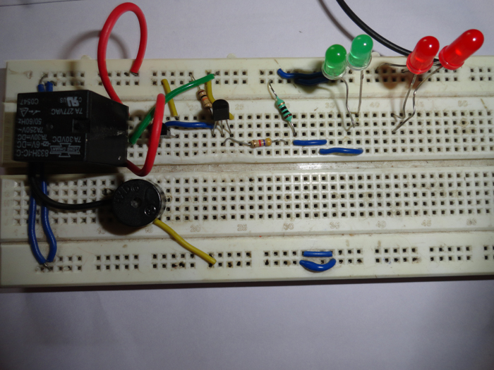
Fig. 1: Prototype of Working of Vehicle Indicator Circuit on Breadboard
Take care while using the value of resistor R1. It should be chosen according to requirement like if you are using LED its value may vary from 100 ohms to 1 K ohms. But if you are connecting the indicator light bulb then chose value of resistor according to the wattage of bulb you are using.
Circuit Diagrams
Filed Under: Electronic Projects

Questions related to this article?
👉Ask and discuss on Electro-Tech-Online.com and EDAboard.com forums.
Tell Us What You Think!!
You must be logged in to post a comment.