This circuit is build around a single IC 4049 which a inverter. The advantage of this circuit is with the help of HF and LF oscillator made around the IC you can produce different sounds such as sound of bird's, a cricket's and you can produce sound of rising/falling siren's by varying the variable resistor.
You can use this circuit as door bell in your homes and offices or it can be used in your vehicle, bicycle as a horn and you can change the sound without adding or removing any components, just vary the variable resistor and get a different sound.
[[wysiwyg_imageupload:11381:]]
Fig. 1: Prototype of Multi Sound Buzzer Circuit on Breadboard
The circuit is based on NOT gate CD4049 IC in this we are utilizing all gates of NOT gate. To understand the working you should know about the truth table of NOT gate are as follows-
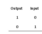
Fig. 2: Truth Table for NOT Gate
CD4049 contain six inverter gates in one package as shown in diagram. In this pin 3 is input pin and 2 is for output for first gate similarly pin 5 is input and pin 4 is output for second gate similarly we have four more gate. In this 1 is for supply voltage and pin 8 is connected to ground and pin 13 and 16 are unused pin.

Fig. 3: Pin Diagram of IC CD4049
Basically the circuit works on two oscillator HF and LF. An oscillator is used to produce periodic or regular repetitive waveform in the form of sine, square, saw tooth or triangular waves. Low frequency oscillator produces waveform at very low frequency generally in the range of 0 – 20 Hz. In this circuit we are using it to modulate the pitch of audio amplifier.
In this circuit HF oscillator is formed using N1, N2 along with VR1, VR2, C1 and C2 in free running astable multivibrator mode and LF oscillator is made with the help of N4, N5, VR3, VR4, C3 and C4. In this circuit N3 and N6 are utilizing as buffer.
For producing different sound properly adjust VR1 and VR2 of HF oscillator. The later may be continued or interrupted and different sounds can be adjusted by varying the variable resistor VR3 and VR4 used in LF oscillator. And transistor T1, T2, T3 and T4 are working as AND gate here means when all four transistor conducts we will get an audio tone. So be careful while adjusting the variable resistor if they made ground it may possible you will not receive any sound.
Circuit Diagrams
Project Components
Project Video
Filed Under: Electronic Projects
Filed Under: Electronic Projects

Questions related to this article?
👉Ask and discuss on Electro-Tech-Online.com and EDAboard.com forums.
Tell Us What You Think!!
You must be logged in to post a comment.