1.1) System
A system is a set of different elements, which are interconnected inside a boundary, and may have abilities of input processing and output.

Fig. 1: Image Illustrating System by Comparison to Solar System
An example of system:
Solar System itself is a good example of a system. Here the elements are planets and sun, interconnected through the force of gravity.
1.2) Electronic System
Electronic System is a system in which the elements are electronic components, which are interconnected through wires or tracks. Here the boundary can be considered as the PCB which holds the components and tracks. The power supplied, or signals applied can be considered as input and the sound, display, movement etc. can be considered as output from the system.
The figure: shows an electronic oscillator system using components like 555 timer IC, regulator, resistor, capacitor, loud speaker etc.

Fig. 2: Image showing Electronic Oscillator System
SBMCS & MCU
1.3) Single Board Micro Computer System (SBMCS)
It can be considered as a complete system which can operate on its own and built in a single board. Each functional block, like the clock generator, bus generator, EEPROM, RAM, USART etc. are implemented usingseparate ICs and all of them are controlled by a single processor IC.
Block diagram of a SBMCS
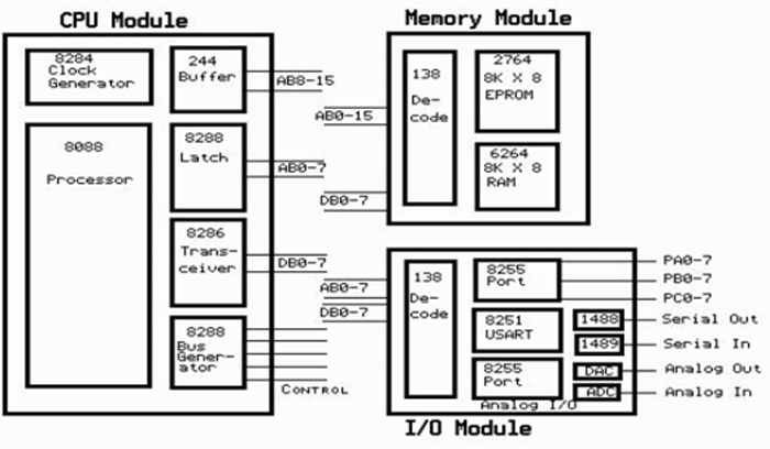
Fig. 3: Block Diagram of a SBMCS
Image of a SBMCS

Fig. 4: Image of a SBMCS
1.4) Microcontroller Unit (MCU)
Suppose we integrate all the modules of a Single Board Microcomputer inside a single chip, then it becomes a Microcontroller. Microcontrollers have the following functional blocks built inside a single IC.
· CPU
· Memory
· Clock generator
· Timers
· ADC
· USART
· IO ports etc.
An example of an ARM-based microcontroller
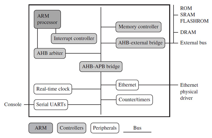
Fig. 5: Image showing an ARM-based Microcontroller System
SOB & SOC
1.5) System on Board (SoB)
A microcontroller is built for general purpose and it can be used for a variety of applications. It can be interfaced with other components like RTC, Keypad controller, USB controller, Camera controller etc. inside a single board to form a System on Board (SoB).
Image of a 8051 base SoB

Fig. 6: Image of a 8051 based SoB
Embedded System and a simple Operating System:
All the microcontrollers can be programmed, and operated as per the instructions in the code which have been loaded into it. The hardware will not function unless the proper code is burnt into it. So if we consider a microcontroller inside a SoB, both the peripherals (hardware) and the program (software) required to operate them are embedded into it. Thus it forms an Embedded System.
The software is the soul of an embedded system. It operates the hardware and hence we can call the software, an Operating System. For SoBs shown above, we require only the simplest form of OS.
A simple OS written in C
Here, an infinite loop is created using while condition, which will keep the controller always running.
Let’s see an example of infinite loop OS blinking an LED,
while ( 1 )
{
led_on ();
delay_ms( 2000 );
led_off ();
delay_ms( 2000 );
}
1.6) System on Chip (SoC)
All the features or more found in the above example of SoB along with the microcontroller itself when integrated into a single IC, it becomes a System on Chip (SoC).

Fig. 7: Typical Image of ARM System on Chip (SoC) IC
Internal block diagram of ARM11 based SoC (S3C6410)

Fig. 8: Internal Block Diagram of ARM11 based SoC (S3C6410)
Why do we need a complex OS?
1.7) Why do we need a complex OS?
Consider the case of the simple infinite loop OS shown in the code . Suppose we need to continuously blink LED1 with a delay of 2 seconds, and also when we press a key, say KEY2, LED2 should turn ON.
while ( 1 )
{
led_1_on ();
delay_ms( 2000 );
led_2_on ();
delay_ms( 2000 );
wait_key_press ();
}
The above code won’t work, because when the code flow reach wait_key_press (), it will just keep on waiting for a key press and the LEDs won’t get ON or OFF unless there is a key press happens.
Of course we can adjust the above code to somehow get this small example working, but when we are doing some useful applications, it just won’t help us a lot.
For the above example, what we need actually is Multitasking.
Multitasking means doing more than one task simultaneously. In the above example there are two tasks, which need to be execute simultaneously
1) Blink an LED
2) Wait for a key press.
Our infinite loop OS has only Single tasking capability. That is one of the main reasons why we need a standard OS, which is complex and have Multitasking capability.

Fig. 9: Image showing Simple OS compared to Complex OS
Introduction to Embedded Linux
2) Introduction to Embedded Linux
2.1) Standard OS and their features
An Operating System is any software which runs on a hardware system and keeps the system operating from the time it boot till shutdown. The Operating System manages system resources, control system services, and provides user interface.
The core part of an Operating System is called Kernel. Kernel is responsible for the basic features which an OS can provide. User or user application can communicate with system hardware only through the kernel layer.
Basic architecture of an OS

Fig. 10: Image showing Basic Architecture of an OS
Features of an OS
· Process management
· Memory management
· I/O system management
· Secondary storage management
· Network interface
· User interface
· File management
· Protection and Security
2.2) Whyshould we choose Linux OS?
The reasons why most of the people chose Linux OS for the embedded device are,
· Linux is a free and open source operating system
· Linux can run on various kind of CPUs
· Linux has a very well structured kernel
· Linux is a highly secure OS
· Linux OS never crash unless there is any hardware problems
· Easy to write device drivers in Linux kernel
· Wide range of software available which are supported by Linux
Embedded Linux System
2.3) Embedded Linux System
An embedded system in which the Linux OS is operating the hardware is called an Embedded Linux System.
The basic architecture of embedded Linux system

Fig. 11: Image showing Basic Architecture of Eembedded Linux System
The core part of any operating system is the kernel. The kernel is responsible for the particular features which operating systems possess. It makes the standard operating system entirely different from the infinite loop operating system.
Architecture of a standard Linux Kernel
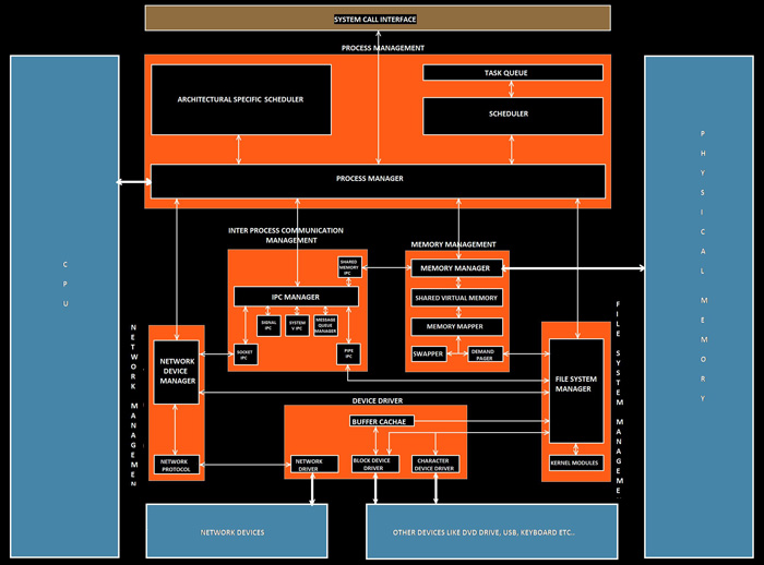
Fig. 12: Image showing Architecture of a Standard Linux Kernel
Kernel Subsystems:
1) Process management – Schedule all the processes and control multitasking
2) Memory Management – Manages the physical memory and provides memory mapping, shared virtual memory, swapping etc.
3) File system Management – Manages the file system including device files
4) Inter-Process Communication – Manages and control the communication between various processes
5) Network Interface – Provides network access to the Linux machine via protocols like TCP, UDP, IPV4, IPV6 etc
6) Device driver – It forms a medium for the communication between various processes with the actual hardware.
WhyARM hardware is widely used?
2.4) Why ARM hardware is widely used?
The Linux kernel have been implemented on different hardware platforms based on x86, ARM, PowerPC, MIPS, SuperH, m68k etc. But in embedded system ARM based processors are widely preferred because of the following reasons,
· ARM processor has a RISC (Reduced Instruction Set Computer) based architecture
· Highly power efficient compared to other kind of processors
· ARM instruction set architecture Licensing allows companies to custom built their ARM based processor
· RISC architecture enables ARM processor to operate at higher clock frequencies.
· High code density is a significant factor since embedded devices have limited memory
· ARM doesn’t have BIOS, the kernel is directly loaded from the flash
· ARM has on-chip debugging capability
ARM has a modified RISC architecture providing high code density as well as low power consumption. The modified RISC architecture of ARM design includes:
· Variable cycle execution
This helps to save power, area, and code size, by reducing the execution cycle for certain instructions
· Thumb 16-bit instruction
This reduced bit of instruction set improves the code density.
· Also includes enhanced instructions for digital signal processing.
Linux Porting
3) Linux Porting
We know that Linux OS supports various kind of hardware architecture. The term OS porting means to modify or customize an OS, which is running on particular hardware architecture, in such a way that it can run on another particular kind of architecture when loaded into one.
We can find Linux OS normally in personal computers. The Linux supporting personal computer mostly use Intel processors, and the architecture of Intel based processors are x86 or x64. But as we mentioned before, most of the embedded devices use ARM based processors. So if we required loading the Linux OS into an embedded device, we must do something that will enable the OS running on x86 based hardware to run on ARM based hardware, and we call it Linux Porting.
Simply, loading and running the Linux from one processor to another processor of different architecture type.
Once ported to ARM architecture, we can call the general purpose GNU/Linux as ARM Linux.

Fig. 13: Image showing Linux Porting
After the porting the general purpose Linux changes to a customized task specific OS. The following changes occurs during the process
· The code footprint reduces below 10 MB; while the general purpose OS have a code footprint of around 500 MB.
· The code become more efficient and fast
· It excludes task specific modules of a general purpose OS are excluded, which are not required in particular hardware.
Linux porting is a wide topic itself, and is the most important step in developing an embedded Linux system. It is also the most difficult step as well. I will try to explain the basics of Linux porting briefly.
Necessary things to be taken care of while Linux porting
Hardware & Firmware
3.1) The Hardware
The architecture of the hardware into which you are going to port Linux should be supported by the Linux kernel. Linux support wide variety of hardware architectures, including ARM architecture.
While selecting the hardware we should take care of the following parameters
· Processor – The processor architecture, processor family, processor model within the processor family, the address from which the processor fetches its first instruction etc.
Board – The board type, model, part number, schematics and most importantly the support available
· RAM – The size of the RAM, its start and end address in physical address space etc.
· ROM – The model of the ROM/Flash chip, its size, start and end address in physical space etc.
· Disk storage – The disk storage size and type available in that board
· Peripherals – Which all peripherals available, their type, model, physical address space and peripheral ID
3.2) Firmware
Firmware is a low-level software which resides in the ROM. It is the first code that execute when the device is powered up. Normally the firmware is just a simple initialization and bootloader routine. It is considered as deeply embedded. It is the first code that should be ported to a new platform.
The choice of firmware depends upon the complexity of the operating system. The main function of the firmware is to load and boot an operating system. Firmware can remain active even if the system is running.
ARM Firmware Suite (AFS) is a firmware package developed by ARM. It supportvarious ARM boards and processors. It has two major parts,
· Hardware Abstraction Layer called ?HAL
· A debug monitor called Angel.
HAL provides a standard API and can communicate with user through USB, Ethernet, or serial. Hence the firmware helps to make the porting a lot more easier.
Functions provided by HAL:
· uHAL initializes and set up the processor core and the system
· It communicate with the user and help in porting process
· Provides periodic interrupt for preemptive context switching OS
· Support various interrupt controllers
Angel interfaces a user’s debugger with the hardware platform.IRQ/FIQ interrupts are used for communication with the debugger.
Functions of Angel:
· Helps in inspect and modify memory
· Download and execute images
· Set breakpoints, and display processor register contents.
The operation of the firmware can be described through the following steps

Fig. 14: Image showing Flowchart Representing Operation of a Firmware
Boot Loader
3.3) Boot Loader
The bootloader, is a small machine dependent code, which runs before the main kernel, and without it the system cannot boot
The functions of bootloader operates in the following manner,

Fig. 15: Image showing Flowchart Representing Operation of Boot Loader
Storage of Bootloader, Kernel and Root file system in the ROM memory. (Flash)

Fig. 16: Image showing data usage of Bootloader, Kernel and Rooot File System in ROM
The x86 architecture supports bootloader for Linux like LILO, GRUB etc. Types of Boot Loaders supporting ARM Linux are;
· Compaq’s bootldr – Mainly for Compaq iPAQ
· blob – Loader from LART hardware project
· RedBoot – Supported by all architectures like x86, ARM, PowerPC, MIPS etc.
· U-Boot – Universal bootloaderbased on PPCBoot and ARMBoot.
The U-Boot can be considered as the standard ARM bootloader. U-Boot is the most popular and actievely developed bootloader.
Its features include:
· It is an open source bootloader
· U-Boot is rich and highly flexible
· It is well documented and have extensive command set
· It can load the kernel from IDE or SCSI disk
Cross compiler & Filesystem
3.4) Cross compiler
A compiler is nothing but a computer program which can convert the code written in the high level language (C, CPP, java etc.) to its executable in low level language (assembly). Usually a compiler runs in a machine of specific architecture compiles code for the same architecture itself.
A compiler does the following steps

Fig. 17: Image showing Flowchart Representing Operation of Cross Compiler
A cross is a kind of compiler program which runs in a system of particular hardware architecture, but can compile codes and generate executable for systems having different hardware architecture.
The compiling using a cross compiler is called cross compiling of the source code.
Operation of a compiler and cross compiler

Fig. 18: Image showing Flowchart Representing Operation of a Compiler and Cross Compiler
For ARM Linux porting we should Re-target our GCC for ARM platform. GCC based cross compiler tool chains are widely used and are available for free. The tool chain needs to be ‘untared’ in /usr/local/arm directory
3.5) Filesystem
Normally the general purpose GNU/Linux support filesystem types like EXT2, EXT3, VFAT etc. But most of them are not supported in ARM/Linux. The filesystem type supported in ARM/Linux include,
· CRAMFS
· JFFS2
· JFFS3
· EXT2 over NFTL
· EXT2 over RAM
· EXT3 over NFTL
Among them CRAMFS is widely used. Features of CRAMFS include
· It has bare minimum feature set
· It is a read-only filesystem
· It is compressible
· The maximum size a file can have is only 16MB
· There are no current or parent directory entries
Getting started with Embedded Linux
4) Getting started with Embedded Linux
So far we have discussed the basics of Embedded Linux. Now it’s time to get started with it. All you need is a development board, bootloader,
cross-compiler and filesystem. For beginners I suggest to get the latest and advanced development board. Later you can switch to some core
boards.
In this article we are going to discuss about ARM11 based OK6410 board. It is a very nice board to start with, has so many features, well described user-manual, and also lot of help available for the board.
Main hardware features of OK6410 board
· Samsung S3C6410 microcontroller based on the ARM1176JZF-S core, main frequency @ 533/667MHz;
· 128MB Mobile DDR RAM;
· 256MB NAND Flash;
· 12MHz?48MHz?27MHz?32.768KH clock source;
· 5V power supply.
· Serial port, Ethernet port, USB port
· One WIFI expansion interface
· SD card slot
· LCD and touch screen interface supporting 4.3” TFT LCD;
· CMOS camera connector
The 6410 is a 16/32-bit RISC microprocessor, which is designed to provide a cost-effective, low-power capabilities and high performance. The memory system has dual external memory ports, DRAM and Flash/ROM. The 6410 includes many hardware peripherals such as a Camera Interface, TFT color LCD controller, 4-channel UART, I2C-BUS interface, USB Host etc.
The internal architecture of 6410, displaying all the available features

Fig. 19: Image showing Internal Architecture of 6410
Steps required in getting the board OK6410 board up
Ubuntu 9.10 with the kernel version 2.6.31 is provided along with OK6410 board. Install the Ubuntu in a virtual machine to avoid risk of system halt and restart due to kernel compiling or other processes. Create a directory “/arm9board” in which will be our main directory inside which all the work should be done.
1) Creating a bootloader
A bootloader U-boot of version u-boot-1.1.6 is provided with the OK6410 board.
Copy the source code “uboot1.1.6_OK6410_v1.0.tgz” to the directory “/arm9board” and unzip it using the following command
tarxzf uboot1.1.6_OK6410_v1.0.tgz
Compile the u-boot bootloader using the following commands
cd uboot1.1.6
make smdk6410_config
make
Now our bootloader named as “u-boot.bin” will be ready and can be found in the directory “uboot1.1.6”.
Contd…2
2) Installing Cross-Compiler
Before cross compiling, we have to install cross compiler tool chains first. A cross compiler is provided with OK6410 board named as “Cross-4.2.2-eabi.tar.bz2”. Copy the code to the directory /arm9board and execute the following commands:
cd /arm9board //enter the directory “arm9board”
mkdir /usr/local/arm //create a directory in “/usr/local/arm”
tarxjvf cross-4.2.2-eabi.tar.bz2 -C /usr/local/arm //un-zip the cross-compiler to //“/usr/local/arm”.
We can find the cross-compiler in the directory “/usr/local/arm/4.2.2-eabi”.
3) Compiling the kernel Image
Linux-26.28 kernel is provided with the OK6410 board. Copy linux2.6.28.tgz to the directory
“arm9board” and un-zip it:
tarxzf linux2.6.28.tgz
Configure the kernel according to your purpose using the following command, which will pop-up a GUI
makemenuconfig
The following command can be use to compile the Linux kernel into “zImage” binary:
makezImage
After the compilation the binary image “zImage” will be found in the directory
“arch/arm/boot”.
4) Loading the boot-loader in the SDcard
For burning the boot-loader into the SD card, a tool called IROM_Fusing_Tool is used. The memory card should be formatted in FAT32 filesystem. Insert a SD card to a card reader and connect the card reader to the PC. Run the IROM_Fusing_Tool.exe in the folder “ToolsSDboot”
In the IROM_Fusing_Tool window, click “Browse” and open the file “OK6410_SDboot.nb0” in the folder “ToolsSDboot”, select the SD drive from the drop-down list and then click the “START” button to start fusing the SDboot image to the SD card.
When the burning is done the IROM’s window appears like this

Fig. 20: Screenshot of IROM’s Window
5) Formatting and flashing the NAND chip
Now insert the SD card in the card slot. Set the device to boot from SD card by setting the toggle switches.
Switch 1 —–à OFF
Switch 2 —–à ON
Switch 3 —–à ON
Switch 4 —–à ON
Run the DNW, a hyper-terminal like program and connect it with the board. Power-On the board, and it we can see the DNW window like the following,
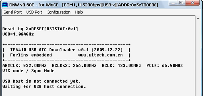
Fig. 21: Screenshot of DNW Hyper-Terminal Program
Now connect the USB cable and install the driver provided with the board. Go to the DNW menu “Configuration->Options” and configure the download address to “0x57e00000”

Fig. 22: Screenshot of DNW’s Configuration Window
Now you can download the bootloader to the OK6410 through “USB Port->Transmit->Transmit”, and opening the file “u-boot.bin”. Quickly press the Space Bar to interrupt the auto-boot to enter the u-boot command menu.

Fig. 23: Screenshot of U-Boot Command Menu
Press “f” to format the NAND Flash.
Once the formatting has been done, press “e” to exit the menu, then type the command below and press Enter:
dnw 50008000

Fig. 24: Screenshot of downloading U-Boot to the RAM
Now let’s download the U-Boot to the RAM through “USB Port-> Transmit-> Transmit” and open “u-boot.bin”.
Now we need to program the U-boot to the NAND, type the following commands one-by-one.
nand write 50008000 0 1000
nand write 50008800 1000 1000
nand write 50009000 2000 1000
nand write 50009800 3000 1000
nand write 5000A000 4000 FE000
Now set the toggle switch for boot from NAND mode
Switch 1 —– OFF
Switch 2 —– ON
Switch 3 —– OFF
Switch 4 —– OFF
Contd…3
6) Burning the Linux kernel
Restart the OK6410 and press any key during quickly while booting to enter the u-boot command menu.
Press “k” and then click “USB Port->Transmit->Transmit”, and open the demo image provided with the board. The Linux kernel will get automatically downloaded and burnt to the NAND Flash.
The DNW window appears like the following
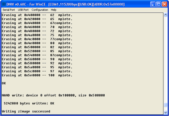
Fig. 25: Screenshot of DNW window
7) Burning the file system
The ARM/Linux 2.6.28 system on the OK6410 supports YAFFS2 and CRAMFS filesystems they are provided with the board like,
OK6410_yaffs2_v1.0.tgz –YAFFS2 filesystem;
OK6410_touch_v1.0.cramfs –CRAMFS filesystem demo that supports touch screen;
OK6410_mouse_v1.0.cramfs –CRAMFS filesystem demo that supports USB mouse;
Restart the board, and press any key while booting to get the u-boot command menu,
Press “c” and download the OK6410_touch_v1.0.cramfs.
The cramfsfilesystem will get automatically downloaded and burnt to the NAND Flash. Once done the DNW window appears like the following

Fig. 26: Screenshot of DNW Window after Downloading cramfsfilesystem
Now we can restart the OK6410.
We will see the touch screen calibration interface on the LCD. Gently touch the cross hairs to calibrate the touch screen. Once the calibration has finished we can see the colorful GUI with touch interface.
Embedded Linux programming
5) Embedded Linux programming
We have successfully made the OK6410 board up and now it’s time to do some programming stuff.
We can do programming mainly for three kind of execution purpose.
· Simple C code executables
· Shell scripting
· Lodable kernel module
You just can’t compile your code in OK6410 board right now, so just edit and compile the code in your PC itself. Make sure that you are compiling for the ARM platform.
5.1) A simple C code example
Let’s try executing the following hello world program.
#include <stdio.h>
int main ()
{
while (1)
Printf ( “nhello worldn” ); //continuously print hello world in the console
}
Save the code as hello.c
You can cross-compile the following code using the command
/usr/local/arm/4.2.2-eabi/usr/bin/arm-linux-gcc hello.c -o hello
An executable file named “hello” will be created in the same directory. You can copy the executable to your OK6410 board and in the terminal to execute, type the following
./hello
5.2) Shell scripting
Shell is a command line interpreter of an OS. We can execute various commands using the command line one by one. A shell script is nothing but an arrangement of the commands required to perform a particular task in a single executable file.
Let’s try creating a shell script for executing the above hello world program.
Use the following command for creating a text file and edit.
cat > hello_script
>./hello
Press enter and ctrl+D to save.
Now make the file executable using the following command
chmod u+x hello_script
Now you can simply ./hello_script to execute our previous hello world program
Loadable kernel module & Conclusion
5.3) Loadable kernel module
A kernel module is a C code which can be separately compiled and inserted into a running kernel. Once inserted the module become a part of the kernel itself and get executed.
An example for a simple kernel module program
#include <linux/kernel.h>
#include <linux/module.h>
int init_module ( void )
{
while ( 1 )
printk ( “nhello worldn” );
return 0;
}
void cleanup_module ( void )
{
Printk ( “nmodule removedn” );
}
Save the program as hello_module.c
Now you can compile the code using make command. But you need a makefile to do that
Save the following code to a file named “Makefile”
obj-m += hello_module.o
all:
make -C /lib/modules/$(shell uname -r)/build M=$(shell pwd) modules
clean:
make -C /lib/modules/$(shell uname -r)/build M=$(shell pwd) clean
Now for compiling, just enter the command
make
When the compilation has been done successfully, you can see so many files in the same directory, among which “hello_world.ko” is the kernel object
To insert the module to the kernel
insmod hello_world.ko
To read the output from your kernel module
dmesg –c
Once you have done with it, don’t forget to remove the module
rmmod hello_world.ko
Conclusion
Embedded Linux is a actively developing and a very vast field. What all things we have discussed or done are simply nothing. But I hope the reader have got the basics related to this field. All we need is to practice a lot, try out and explore things by our own.
Few Steps suggested are:
· Cross compile a general purpose OS for ARM platform.
· Write drivers for the peripherals like, UART, Ethernet, LCD controller etc.
· Switch to some core boards having only controller and memory and try to up the system by designing a making the hardware, and write drivers for the same
Filed Under: Tutorials


Questions related to this article?
👉Ask and discuss on Electro-Tech-Online.com and EDAboard.com forums.
Tell Us What You Think!!
You must be logged in to post a comment.