In this tutorial, we will learn how to interface EMG (electromyography) sensor with Arduino. Electromyography is the study of muscles, particularly in the electrical domain. Measuring the electrical signals generated by stretching and contracting muscles.
We will use Myoware(by Advancer technologies) EMG sensor in this tutorial. Advancer Technology is a startup whose main area of interest is EMG hardware development. Their Myoware EMG sensor kits are open source. Plenty of Myoware kit copies are available on the internet. We will use the one produced by SparkFun.
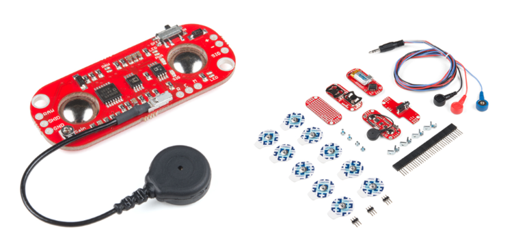
SparkFun provides many accessories with the main sensor module, a great resource to learn to debug and develop EMG applications. The main sensor module parts and pinout are below.
The sensor operates on +3.3 to 5 volts. The output is in two forms. The first one is the raw EMG signal. Another one is the filtered output signal. The filtered signal is compatible with Arduino. We will use the filtered output in this tutorial. The output voltage depends on the input. If the input is 5 volts, then output by the sensor will range between 0 to 5 volts. The main components of EMG sensor are
- Electrodes – Used to measure the electrical signal change during the expansion and contraction of muscles.
- Condition and Rectification – Bring the signal in a digitally readable form.
- Amplifier – Increases the strength of the signal generated by the muscle.
EMG controlled wheelchair
Let’s build a wheelchair for a disabled person controlled by an EMG sensor using Arduino Uno. Imagine that a disabled person can move his/her neck in all directions.
Four dc motors drive the wheelchair. EMG sensor is connected to the neck muscle of the disabled person. The idea is that when the person moves his neck right, the wheelchair turns right, moves left chair turns left. Forward and backward on neck bending and upwards.
Place the electrodes one on the Trapezius muscle. The other two on the sternocleidomastoid muscle around the neck.
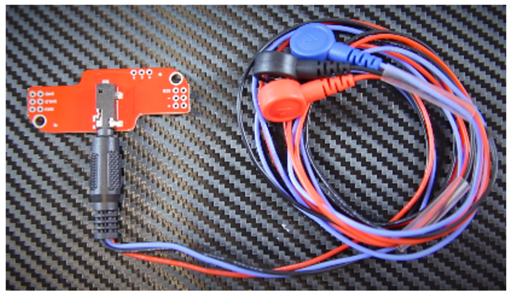
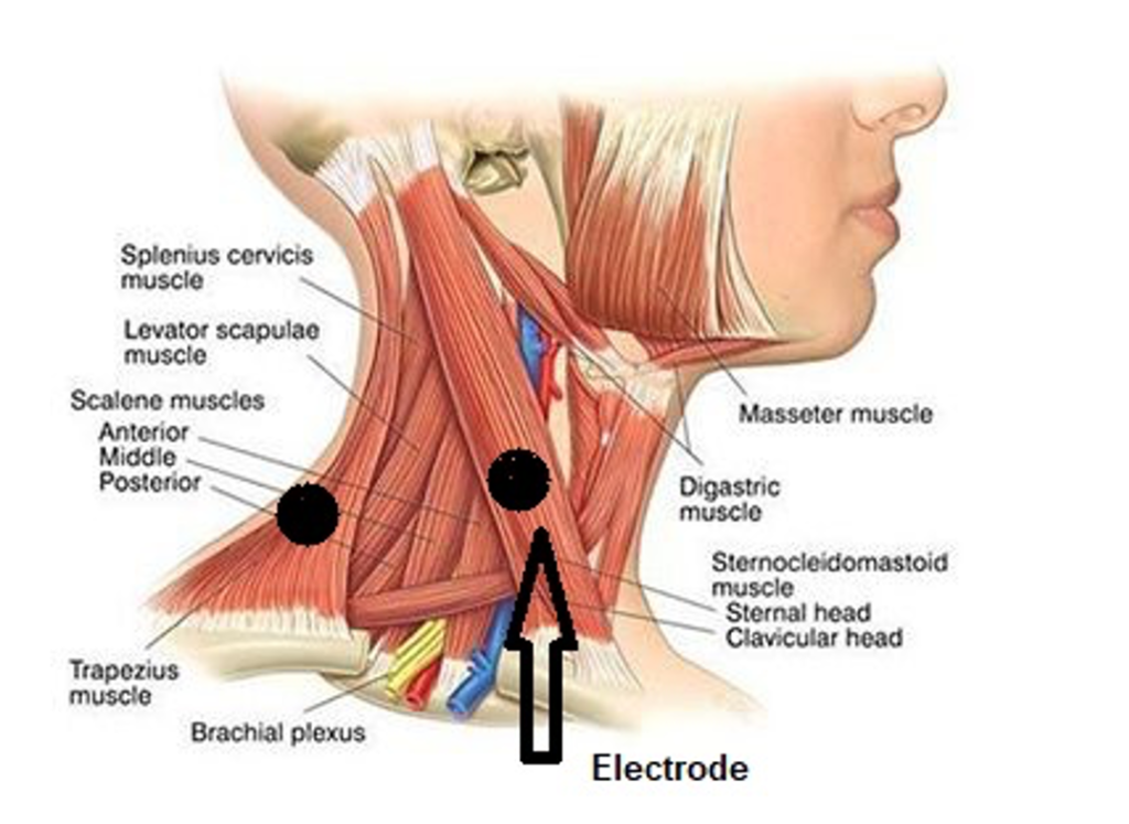 Myoware offers one electrode only. Using the SparkFun EMG electrode shield, you can work with three electrodes at a time. Stack the shield on top of the main shield and insert the electrodes pin in the audio jack. Multiple electrodes provide high resolution.
Remember to attach pads with electrodes. Pads are one-time usable once removed from the body. You must dispose of them.
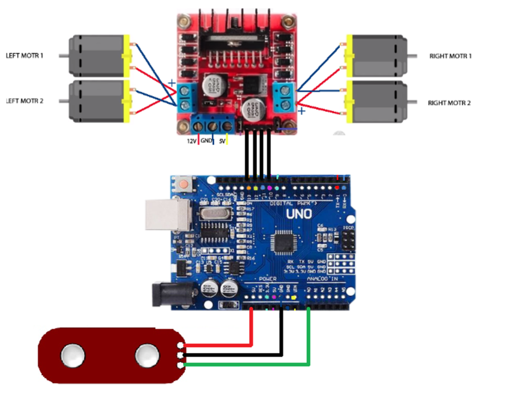
Project circuit diagram
Dc motors are connected to the motor driver. Arduino power is not sufficient for motors, so an external driver is compulsory. External drivers have a flyback diode to protect Arduino GPIO’s from back emf. Driver input power is 12 volts. It can easily drive four 12-watt motors. Arduino digital pins 10,11,12, and 13 are controlling motors. Myoware sensor is powered with Arduino 5-volt output. Sensor output is input to analog 0 pins of Arduino.
Project code
Myoware output is a signal ranging between 0 to 5 volts since we powered it through Arduino. The analog output from the sensor is mapped between the Arduino analog range of 0 to 1023. Motors are driven based on this signal.
Motors are divided into two groups, right and left. To move forward, rear-wheel motors are drive. For backward, front-wheel motors are driven. To turn right front right motor is driven and last for the left forward left motor is started.
The system behaves like controlling a rover car.
Limitations: Adjusting the gain and Myoware response is complex. Quick movement and spikes are dangerous in medical applications. One way to overcome speedy response is running the motors slowly. PWM (pulse width modulation) signal to motors will reduce the motor speed, eventually decreasing the chair movement.
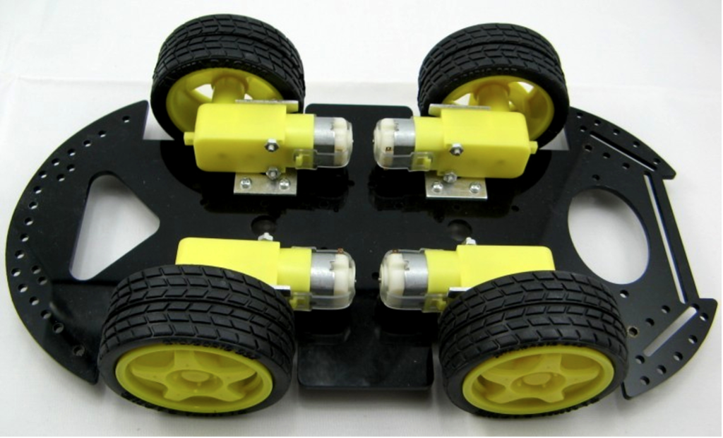
Let’s DIY this Project. Try it on the rover platform: Where to purchase parts?
Myoware: Mouser electronics
Arduino: Mouser electronics
Vehicle development platform : DigiKey
Motor driver: Mouser electronics EMG
You may also like:
Filed Under: Arduino, Microcontroller Projects



Questions related to this article?
👉Ask and discuss on EDAboard.com and Electro-Tech-Online.com forums.
Tell Us What You Think!!
You must be logged in to post a comment.