In the previous article, we learned about EMI/EMC pre-compliance test. EMS/EMC pre-compliance immunity test is required before the compliance test.
EMS/EMC pre-compliance immunity test will give the confidence to pass the compliance test. The pre-compliance immunity test simulates all the tests done at the compliance test lab, but it is unnecessary to apply all the tests on equipment under test (EUT). The test depends upon the application and EMC regulatory standards of the country. Given that the compliance test is costly, all troubleshooting should be solved in the pre-compliance test.
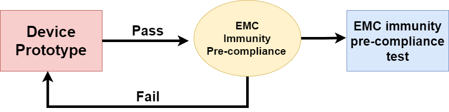
Fig.1 Block diagram of Pre-compliance test
This article is about different EMS/EMC pre-compliance immunity tests and how these tests can be performed at small labs. Many labs provide immunity tests, but this article tries to make a simple and most straightforward setup for different types of tests.
Type pre-compliance immunity tests
As discussed in a previous article, EMS/EMC immunity test is performed to ensure that the device can survive the different interference generated by other devices. The most common EMS/EMC immunity tests are given below in the block diagram.
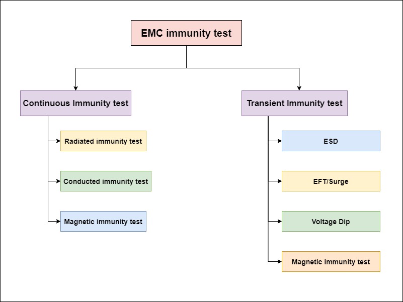
Fig. 2 Block diagram of immunity test
Continuous immunity test
Radiated pre-compliance immunity test
Radiated emission is electromagnetic RF signals produced by devices in the environment. Mobile, TV, and other devices generate electromagnetic interference through the air, which can be a serious problem for the other devices. The radiated pre-compliance immunity test simulates this condition to test the device in a simulated environment before going to a compliance test.
To perform this test, require an RF signal generator that generates an RF signal and an amplifier to amplify the signal. The output of the amplifier is connected to Antenna to transmit the signals over EUT.
RF signal generator
To perform this immunity test, we need to generate an RF signal transmitted on EUT(equipment under test). But if the frequency range cannot fulfill the device requirement, the big expensive RF signal generator will work great to achieve the range of the device.
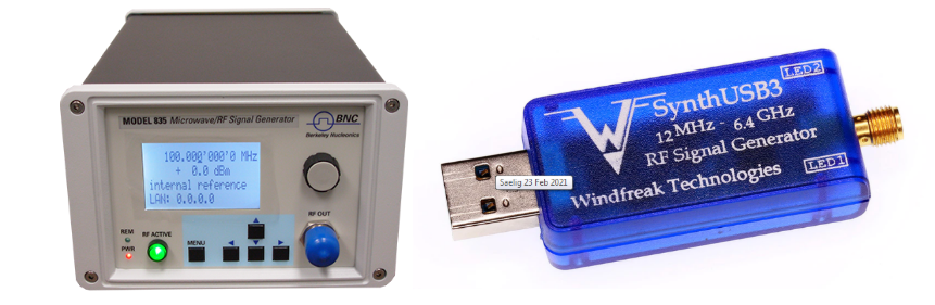
Fig. 3 RF signal generator
RF signal amplifier
RF amplifier is used to get more gain in the signal. The amplifier depends upon the requirements and output device need. The amplifier shown in the image has a gain of +20db.
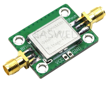
Fig. 4 RF signal amplifier
EMC probes
EMC probes are used to detect electromagnetic interference in circuits, but they can be used as an antenna to transfer RF signals to the device. Connect the RF signal generator with these probes through an RF amplifier and test immunity and signal variation by hovering the probe on the circuit. This process is very affordable and easy to set up.
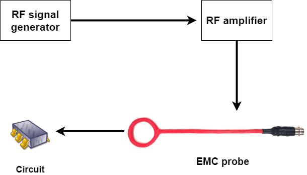
Fig.5 EMC Immunity test by EMC probe
TEM cell
TEM cell stands for “Transverse-Electromagnetic cell” and is the second most affordable equipment for radiated immunity test but a little expensive than EMC probs. The frequency range depends upon the geometry of the cell —the larger has a lower frequency range, but the smaller cell has a higher frequency range. The diagram below shows the signal generator connected to an amplifier which will be connected to a TEM cell that has 50 Ohm resistance at another end.
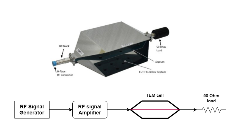
Fig. 6 TEM cell for immunity test
Conducted pre-compliance immunity test
A connected immunity test is performed at the AC or DC power cables. In this test, an RF signal is injected into cables to test the immunity of the device. Similar to the radiated immunity test, an RF signal generator is used to generate signals. The generated signal is amplified by an RF power amplifier. The amplified signal will be injected into the cables of EUT by the transducer (CDN, BCI probe, or EM clamp).
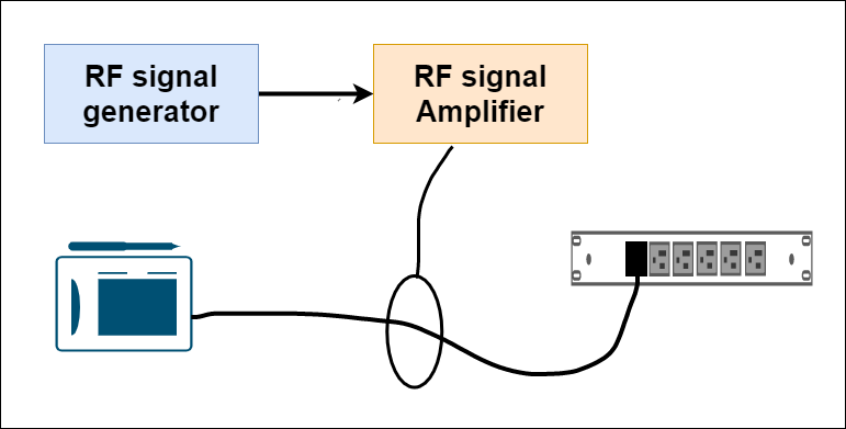
Fig. 7 Conducted pre-compliance immunity test
Magnetic pre-compliance immunity test
In the magnetic pre-compliance immunity test, the equipment is placed in between magnetic fields to check immunity. The testing setup consists of a variac, current transformer, and loop antenna. The setup is the same for both transient and continuous immunity tests.
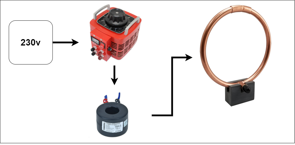
Fig. 8 Magnetic pre-compliance immunity test
Transient immunity test
ESD pre-compliance immunity test
ESD stands for electrostatic discharge—a sudden flow of electricity between two electrically charged objects commonly discharged through the human body. This test can be performed by an ESD simulator device.
There should be a ground reference plane provided on the floor of the lab in the test setup. The grounding system should be connected to the shell of the Equipment under test. There is two coupling plane is used as shown in the image. One is horizontal and another one is vertical. An insulation sheet is placed in between horizontal planes.

Fig. 9 ESD simulation setup
To simulate the ESD, we can use low-cost camping lighter to perform ESD immunity test. The camping lighter can produce hundred or thousand of volts, which is enough to generate spark between conductive surfaces.
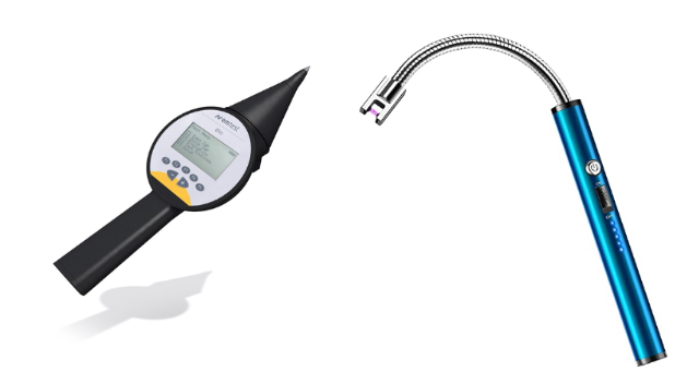
Fig. 10 ESD simulation device
EFT pre-compliance immunity test
EFT stands for electrical fast transient is caused by switching the inductive loads like motors, switches, and relays. A burst generator is used to simulate the switching of inductive load. An EFT burst generator generates bursts of a specific time, frequency, and amplitude to perform this test. That generated burst of the pulse is injected into the device via a capacitive clamp. You can buy or make the capacitive clamp.
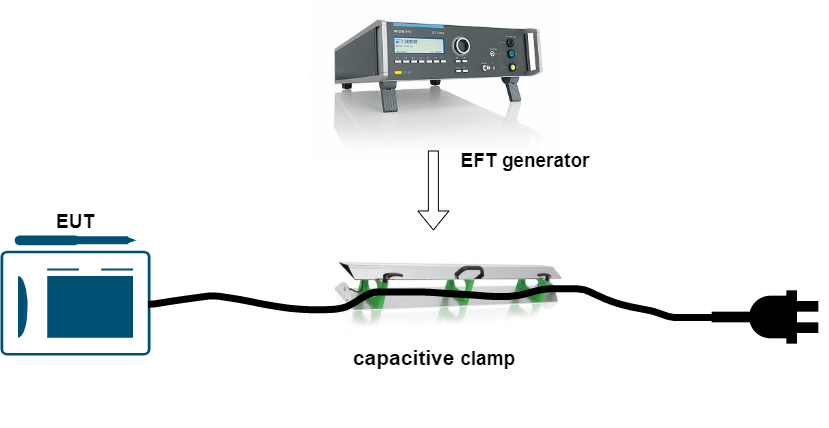
Fig. 11 EFT test
Surge pre-compliance immunity test
A surge test is used to simulate the lightning effect on the AC power supply and is performed on longer cables. This test includes voltage around kV and current around hundreds of Amps. For the surge pre-compliance immunity test, you need a surge generator. There is some equipment available in the market which can generate EFT, surge, and electromagnetic waves. The generated surge is injected by coupling decoupling network device.

Fig. 12 Surge pre-compliance test setup
The frequency spectrum of the surge test is lower than the EFT and ESD test, so the test setup does not need a reference plane. But it does require an earth one.
Volage dip pre-compliance immunity test
In the voltage dip pre-compliance test, we simulate voltage dips (instant voltage drop) over a specific time. The instant voltage drop for a specific percentage can be mimicked by automatically controlled variac and the time of dips is controlled by the UCS500N5 immunity test generator.
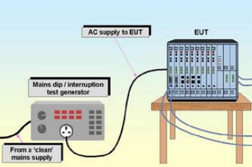
Fig. 13 Voltage dip pre-compliance test
You may also like:


Filed Under: EMI/EMC/RFI, Tutorials
