Summary:
This tutorial is to make reader to understand how to use the Arduino IDE for the development of ESP8266 WiFi Transeivers. This article touches step by step instructions to make the Arduino IDE portable and compatible for ESP8266 boards. As this will be fully Portable installed, you can avoid the way Arduino is installing traditionally. All your Arduino IDE, including ESP8266 extension, sketches, installed libraries will be located only under one folder. And yes, your install location can be in this case a USB Stick/SD Card or external HDD/SSD Drive so you that the installed Arduino IDE and your projects can be transferred everywhere and plug and play.
Installing Arduino IDE:
Step 1: Download the latest ZIP file version of the Arduino IDE from this link
http://www.arduino.cc/en/Main/Software
Step 2: Create a folder named ESP8266 and extract the ZIP file inside this folder.
Step 3: Open the Arduino IDE and
– Go to File
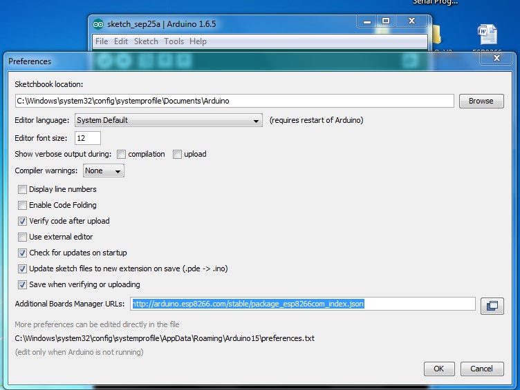
– Preferences – in the Preferences window, go to “additional boards manager URL’s” where you need to paste the following link:
http://arduino.esp8266.com/stable/package_esp8266com_index.json

Fig. 1: Screenshot of Preferences Window in Arduino IDE
– Click OK button.
– Go to Tools
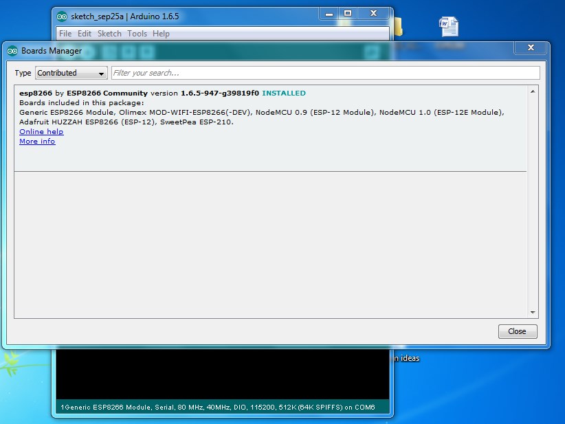
– Boards – > Boards manager, in the Boards manager window, select “contributed” from the TYPE drop
– Select ESP8266 by ESP8266 community forum and version 1.6.2
– Press Install.

Fig. 2: Screenshot of Board Manager Window in Arduino IDE
– Restart IDE
– Select your board as GenericESP8266 Module.
– Leave other Settings unchanged.
– Select your Serial port and upload speed. Keep the usual 115200 baud for more solid upload results.
Entering into Programming mode:
To get the ESP-01 entered into the firmware flash mode, we have to make some changes in the state of the GPIOs. Schematic of the board in TOP orientation is shown in below.
Fig. 3: Image showing Schematic of the ESP-01 Board
|
|
|
|
Connections for Normal mode:
The connection details are as below:
|
WIFI Module |
USB-TTL
|
|
Vcc |
3.3v |
|
Gnd |
Gnd |
|
TX |
RX |
|
RX |
TX |
|
CH_PD |
Connected to 3.3v to enable chip firmware boot |
Don’t forget to pull up CH_PD HIGH, you won’t get a response from the module if it is not done. Since two pins need to be connected to 3.3v it’s easiest to either use a breadboard with some connector cables.
Connections for Programming mode:
To get into the firmware flash mode, we need to make an additional connection, the easiest is to use a breadboard for this.
ESP-01 GPIO0 – Pull low by connecting to ground / minus
When you reboot the module it should be in the firmware flash mode!
Now you can upload your code from Arduino IDE by clicking upload button.
Blink Test:
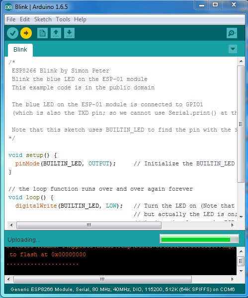
Now go to the File → Examples → ESP8266 menu and load the “Blink” sketch into an editor window. Then hit the upload button.

Fig. 4: Screenshot of the Arduino Code used to Blink an LED
After completion of uploading, disconnect the GPIO 0 pin and make the following connections and reset the board.
This will set the ESP-01 in normal operating mode and inbuilt blue LED will start blinking.
Filed Under: Tutorials


Questions related to this article?
👉Ask and discuss on Electro-Tech-Online.com and EDAboard.com forums.
Tell Us What You Think!!
You must be logged in to post a comment.