Esp8266 is a wifi soc(system on chip) with a built in TCP/IP stack. The chip can host a server and can be used as a stand alone client. Esp8266 is programmed using its uart serial interface. Esp8266 can be programmed OTA(over the air) and by uart interface. For this tutorial we are only going with the uart interface. FT232 is a versatile adapter, its function is to transfer data from usb to uart. It serial interface supports 7/8 data transfer bits,1/2 stop bit,parity check mark/space check and without check.
Before beginning any further i consider that you have already installed the esp8266 core files for arduino ide. If not than here is a good tutorial. http://esp8266.github.io/Arduino/versions/2.0.0/doc/installing.html. I also consider that you have installed the drivers for the ft232 module if not than follow the tutorial. https://learn.sparkfun.com/tutorials/how-to-install-ftdi-drivers/all
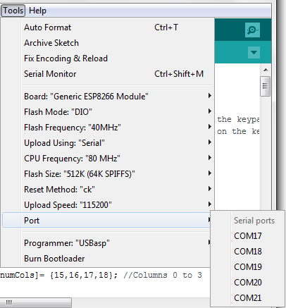
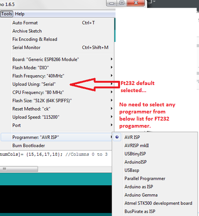
I used an esp8266-01 board for the project. Code is written in arduino Ide and uploaded to esp8266 flash using ftdi ft232 usb to uart module. Esp8266 supports upload speeds of 9600, 57600, 115200, 256000, 921600 bps. The ideal speed is 115200 bps. Speeds greater than 115200 are less likely to communicate and errors originates at speeds higher than 115200 bps. So i will recommend to only upload the code at speed of 115200 bps. I am also uploading code to esp8266 at this speed for this tutorial. Code uploading speed and other settings are shown in the figure below. I am using ESP-01, so i selected Board: “Generic ESP8266 Module”. Select the right port occupied by the ft232 module, before uploading the code.
Note: In the figure on the right side. Uploading option is selected as serial. When the uploading method is serial and we are using ft232 for uploading code then we do not need to select any programmer. The serial is default uploading method and selecting any programmer will not effect the uploading process.
Esp8266 upload code with FT232 programmer Settings- Arduino Ide
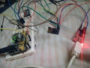
Connection diagram between ft232 and esp8266 wifi module
The above circuit is used to program the esp8266 wifi module with ft232 usb to uart converter and arduino ide. Esp8266 is supplied power by an external 5v power supply. I used LM7805 regulator to convert 12v input to 5v output. At output i connected two diodes in series to drop around 1.4 volts. The remaining voltage 3.7v almost is supplied to esp8266 module.
Connections:
Rx of esp8266 with Tx of ft232.
Tx of esp8266 with Rx of ft232.
Ground GPIO-0 of esp8266.
Make ground of both Esp8266 and ft232 common.
Vcc and CH_PD common.
Note: Powering esp8266 with ft232 and uploading code does not worked for me. Powering the esp8266 module externally solves the problem.
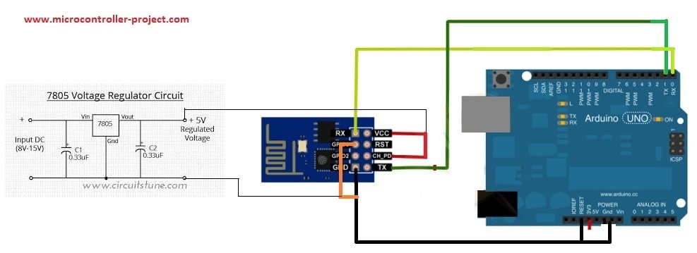
Connection diagram Esp8266 with Arduino uno
Connections:
Rx of esp8266 with Rx of Arduino. (Note: The connection difference)
Tx of esp8266 with Tx of Arduino. (Note: The connection difference)
Ground GPIO-0 of esp8266.
Vcc and CH_PD common.
Make ground of both Esp8266 and Arduino common.
Connect arduino reset to ground to by pass the uploading to arduino uno and make arduino continuously in reset mode.
Select the “Generic esp8266 board” from boards.
Select the arduino port.
Programmer as “AVR ISP”
I am able to upload code easily but some newbies says it didn’t worked for them. I recommend that if the method did not worked for you take this you tube tutorial. https://www.youtube.com/watch?v=P_ecAFpUADU.
Esp8266 Blink example
Watch the Project video Here
Filed Under: ESP8266., Microcontroller Projects


Questions related to this article?
👉Ask and discuss on Electro-Tech-Online.com and EDAboard.com forums.
Tell Us What You Think!!
You must be logged in to post a comment.