Explanation of Basic Clipper Circuit in Detail
In this article I will explain a very basic circuit of Clipper using simple components. Clipping circuit is a wave-shaping circuit and is used to either remove or clip a portion of the applied wave in order to control the shape of the output waveform.
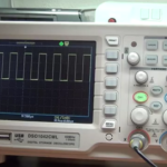
A circuit of clipper with its output and input waveform is shown below.
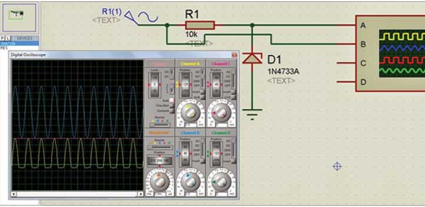
One of the most basic clipping circuits is the half-wave rectifier. A half-wave rectifier clips either the negative half cycle or the positive half cycle of an alternating waveform, and allows passing of only one half cycle.
Such a circuit has great applications in radars, digital computers and other electronic systems for removing unwanted portions of the input signal voltages above or below a specified level. Another application is in radio-receivers for communication circuits where noise pulses that rise well above the signal amplitude are clipped down to the desired level.
Clipping circuits are also referred to as voltage limiters, amplitude selectors, or slicers. A simple diode is used to clip in clipping circuits.
You may also like:
Project Components
Filed Under: Electronic Projects




Questions related to this article?
👉Ask and discuss on EDAboard.com and Electro-Tech-Online.com forums.
Tell Us What You Think!!
You must be logged in to post a comment.