I am going to use Pic18f4550 microcontroller for this tutorial and i am utilizing its timer-0 for detecting the square wave signal rising and falling edges. Timer-0 offer many features and we can use them for different applications. Timer-0 offer following features
- Software select-able operation as a timer or counter in both 8-bit or 16-bit modes
- Readable and writable registers
- Dedicated 8-bit, software programmable prescaler
- Select-able clock source (internal or external)
- Edge select for external clock
- Interrupt on overflow
Timer-0 of pic18f4550 can be used in 8-bit and 16-bit mode. Timer-0 is controlled with T0CON register. T0CON contains the individuals bits that are used to set timer in different modes and other working configurations. T0Con is an 8-bit register. Individual bits with corresponding characteristics are shown below.
|
TMRON: To activate timer-0 we write 1 to this bit and to deactivate timer we write 0 to it. This bit can individually be accessed by the statement T0CONbits.TMR0ON in Mplabx ide.
T08BIT: This bit is used to select between 8-bit or 16-bit timer. Write 1 to it for 8-bit timer counter.Write 0 for 16-bit timer counter. T0CS: Select timer-0 clock source. Internal or external clock. T0SE: Timer 0 edge trier transition selection. Write 1 to this bit for High-to-Low transition and 0 for Low-to-High transition. |
Timer-0 T0CON Timer Control register bits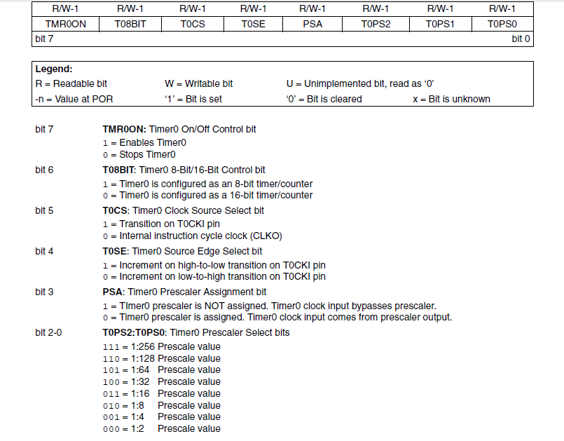
T0CON Timer-0 control bits register of pic microcontroller
|
|
PSA: Timer-0 Prescaler assignment bit.
T0PS2:T0PS0: Timer-0 prescaler value selection bits. T0CON is readable and writable register. We can read this register and can also write to it. Not only whole port we can read and write its individual bits. |
T0CKI Timer-0 Clock Input Pin
Practical example
The statement INTCONbits.TMR0IF is checking the timer overflow flag. The TMR0IF flag bit is present in the Interrupt control register INTCON. when the TMR0L value increases 255 the timer overflow interrupt will occur. Since we are using the timer in 8-bit mode the maximum count for timer will be 2^8 = 255. After 255 the timer will through overflow interrupt. So the above statement is checking the timer overflow flag if it happens the code switches off the timer and clear the timer over flow flag, then starts again from 0.
|
Note: According to the pic microcontroller datasheet at least one rising/falling edge must be registered prior to the first increment edge. Means that the counter will start counting the edges once the first edge is passed away OR the counter will not start counting the edges if a first edge is not detected. The output edge count will always 1 less due to the above behavior of the counter. One can increment the final count by it self. In my code i did not added 1 in final count.
|
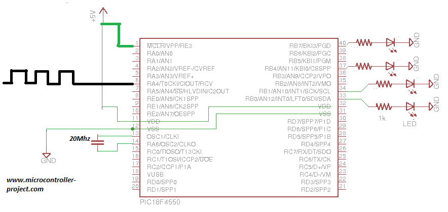
Frequency Edge detection using Pic microcontroller
|
Circuit diagram of the project is given on the left side. Led’s are connected to Port-B of microcontroller. T0CKI pin is connected square eave external signal input from frequency generator.
Scope of the project:
The upper tutorial is valuable only for calculating the low frequencies. At higher frequency levels the 8-bit timer register will overflow very immediately. You can also use timer in 16-bit mode for higher frequencies which can count up to 65535, but still 65535 is not a huge number in counting higher square wave signal frequencies.
Filed Under: Microcontroller Projects, PIC Microcontroller.

Questions related to this article?
👉Ask and discuss on EDAboard.com and Electro-Tech-Online.com forums.
Tell Us What You Think!!
You must be logged in to post a comment.