Engineers Garage

  • Electronic Projects & Tutorials
    • Electronic Projects
      • Arduino Projects
      • AVR
      • Raspberry pi
      • ESP8266
      • BeagleBone
      • 8051 Microcontroller
      • ARM
      • PIC Microcontroller
      • STM32
    • Tutorials
      • Audio Electronics
      • Battery Management
      • Brainwave
      • Electric Vehicles
      • EMI/EMC/RFI
      • Hardware Filters
      • IoT tutorials
      • Power Tutorials
      • Python
      • Sensors
      • USB
      • VHDL
    • Circuit Design
    • Project Videos
    • Components
  • Articles
    • Tech Articles
    • Insight
    • Invention Stories
    • How to
    • What Is
  • News
    • Electronic Product News
    • Business News
    • Company/Start-up News
    • DIY Reviews
    • Guest Post
  • Forums
    • EDABoard.com
    • Electro-Tech-Online
    • EG Forum Archive
  • DigiKey Store
    • Cables, Wires
    • Connectors, Interconnect
    • Discrete
    • Electromechanical
    • Embedded Computers
    • Enclosures, Hardware, Office
    • Integrated Circuits (ICs)
    • Isolators
    • LED/Optoelectronics
    • Passive
    • Power, Circuit Protection
    • Programmers
    • RF, Wireless
    • Semiconductors
    • Sensors, Transducers
    • Test Products
    • Tools
  • Learn
    • eBooks/Tech Tips
    • Design Guides
    • Learning Center
    • Tech Toolboxes
    • Webinars & Digital Events
  • Resources
    • Digital Issues
    • EE Training Days
    • LEAP Awards
    • Podcasts
    • Webinars / Digital Events
    • White Papers
    • Engineering Diversity & Inclusion
    • DesignFast
  • Guest Post Guidelines
  • Advertise
  • Subscribe

Fading LEDs

By Ashutosh Bhatt June 13, 2013

This Fading LED circuit described here is used to develop a fake alarm. In this, LED's glow slowly, become brighter and again dims slowly. This circuit is based on LM358 IC which is operational amplifier. LM358 consist of two independent high gain operational amplifier in one package. Important feature of this IC is that we don't need  independent power supply for  working of each comparator for wide range of power supply. LM358 can be used as transducer amplifier, DC gain block etc. LM358 has large dc voltage gain of 100dB. This IC can be operated on wide range of power supply from 3V to 32V for single power supply or from ±1.5V to ±16V for dual power supply. And it also support large output voltage swing.


LM358 consist of two independent, High gain operational amplifier in one package. Important feature of this IC is we do not require independent power supply for working of each comparator for wide range of power supply. LM358 can be used as transducer amplifier, DC gain block etc. LM358 has large dc voltage gain of 100dB. This IC can be operated on wide range of power supply from 3V to 32V for single power supply or from ±1.5V to ±16V for dual power supply. And it also support large output voltage swing.

Pin configuration of IC is shown below-
Pin Diagram of LM358 Ic
Fig. 2: Pin Diagram of LM358 IC
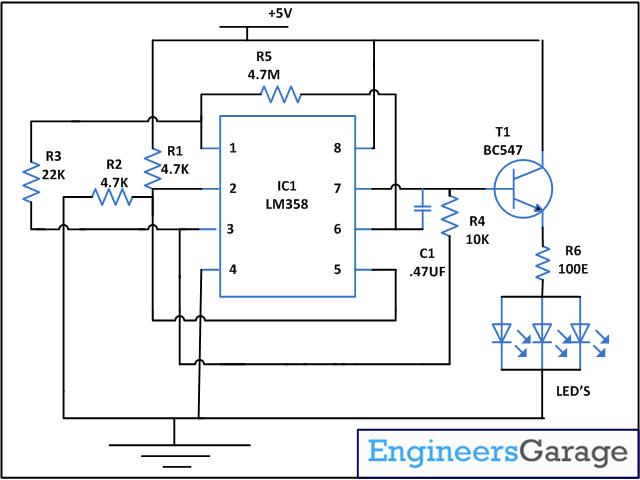
The circuit described here uses an opamp to produce a triangle wave, because of this triangular wave LED’s glow slowly, get brighter and then slowly become off. Similar cycle is repeated. From the above figure you can see that opamp has two input and one output in one independent LM358. Pin 2 (positive pin) and 3 (negative pin) are the input points. Positive pin is used for positive feedback and negative pin is used for negative feedback. In ideal condition when no feedback is applied gain of the opamp would be infinite. When voltage at pin 2 is more than voltage at pin 3 it will raise the output towards the positive maximum voltage and a slight increase at negative pin compared to positive pin will lower the output towards the negative to maximum. This feature of opamp makes it suitable for the purpose of level detection.
The voltage level required for detection can be applied on either of the input pins and the voltage to be detected is applied on the other pin. In our circuit we are applying voltage on positive pin and voltage to be detected is detected on negative pin. When input voltage is applied, positive pin slightly rises above the voltage on negative pin. The output suddenly rises to the positive maximum and remains positive until the input voltage falls below the level to be detected. This is the phenomenon used in the circuit. In this capacitor C1 and Resistor R5 is used as timing components. Capacitor charges and discharges and according to it pin 3 become high and low with reference to pin 2 and we get the desire output. Transistor T1 is used to amplify the signals to drive the LED’s and resistor R6 is used as current limiter to protect LED’s.

Circuit Diagrams

Circuit-Diagram-Fading-LEDs

Project Components

  • Capacitor
  • LED
  • Resistor
  • Transistor BC547

Project Video


Filed Under: Electronic Projects
Tagged With: Fading LED, lm358
 

Next Article

← Previous Article
Next Article →

Questions related to this article?
👉Ask and discuss on Electro-Tech-Online.com and EDAboard.com forums.


Tell Us What You Think!! Cancel reply

You must be logged in to post a comment.

EE TECH TOOLBOX

“ee
Tech Toolbox: 5G Technology
This Tech Toolbox covers the basics of 5G technology plus a story about how engineers designed and built a prototype DSL router mostly from old cellphone parts. Download this first 5G/wired/wireless communications Tech Toolbox to learn more!

EE Learning Center

EE Learning Center
“engineers
EXPAND YOUR KNOWLEDGE AND STAY CONNECTED
Get the latest info on technologies, tools and strategies for EE professionals.

HAVE A QUESTION?

Have a technical question about an article or other engineering questions? Check out our engineering forums EDABoard.com and Electro-Tech-Online.com where you can get those questions asked and answered by your peers!


RSS EDABOARD.com Discussions

  • Finding past posts on edaboard?
  • I think i have devised a new type of "super_transformer" for the Electricity grid?
  • Industrial Relay Board Design for Motorcycle Use
  • sequence detector FSM design
  • Need suggestions in task NI6363 retrigger (analog trigger)

RSS Electro-Tech-Online.com Discussions

  • Sump pit water alarm - Kicad 9
  • Pic18f25q10 osccon1 settings swordfish basic
  • Anyone jumped from Easyeda std to Easyeda pro?
  • turbo jet fan - feedback appreciated.
  • More fun with ws2812 this time XC8 and CLC

Featured – LoRa/LoRaWan Series

  • What is the LoRaWAN network and how does it work?
  • Understanding LoRa architecture: nodes, gateways, and servers
  • Revolutionizing RF: LoRa applications and advantages
  • How to build a LoRa gateway using Raspberry Pi
  • How LoRa enables long-range communication
  • How communication works between two LoRa end-node devices

Recent Articles

  • How IoT network topologies work
  • The top five AI startups to watch in 2025
  • STMicroelectronics unveils SoC based on secure MCU
  • Nexperia’s 48 V ESD diodes support higher data rates with ultra-low capacitance design
  • Taoglas releases Patriot antenna with 18 integrated elements covering 600 to 6000 MHz

EE ENGINEERING TRAINING DAYS

engineering

Submit a Guest Post

submit a guest post
Engineers Garage
  • Analog IC TIps
  • Connector Tips
  • Battery Power Tips
  • DesignFast
  • EDABoard Forums
  • EE World Online
  • Electro-Tech-Online Forums
  • EV Engineering
  • Microcontroller Tips
  • Power Electronic Tips
  • Sensor Tips
  • Test and Measurement Tips
  • 5G Technology World
  • Subscribe to our newsletter
  • About Us
  • Contact Us
  • Advertise

Copyright © 2025 WTWH Media LLC. All Rights Reserved. The material on this site may not be reproduced, distributed, transmitted, cached or otherwise used, except with the prior written permission of WTWH Media
Privacy Policy

Search Engineers Garage

  • Electronic Projects & Tutorials
    • Electronic Projects
      • Arduino Projects
      • AVR
      • Raspberry pi
      • ESP8266
      • BeagleBone
      • 8051 Microcontroller
      • ARM
      • PIC Microcontroller
      • STM32
    • Tutorials
      • Audio Electronics
      • Battery Management
      • Brainwave
      • Electric Vehicles
      • EMI/EMC/RFI
      • Hardware Filters
      • IoT tutorials
      • Power Tutorials
      • Python
      • Sensors
      • USB
      • VHDL
    • Circuit Design
    • Project Videos
    • Components
  • Articles
    • Tech Articles
    • Insight
    • Invention Stories
    • How to
    • What Is
  • News
    • Electronic Product News
    • Business News
    • Company/Start-up News
    • DIY Reviews
    • Guest Post
  • Forums
    • EDABoard.com
    • Electro-Tech-Online
    • EG Forum Archive
  • DigiKey Store
    • Cables, Wires
    • Connectors, Interconnect
    • Discrete
    • Electromechanical
    • Embedded Computers
    • Enclosures, Hardware, Office
    • Integrated Circuits (ICs)
    • Isolators
    • LED/Optoelectronics
    • Passive
    • Power, Circuit Protection
    • Programmers
    • RF, Wireless
    • Semiconductors
    • Sensors, Transducers
    • Test Products
    • Tools
  • Learn
    • eBooks/Tech Tips
    • Design Guides
    • Learning Center
    • Tech Toolboxes
    • Webinars & Digital Events
  • Resources
    • Digital Issues
    • EE Training Days
    • LEAP Awards
    • Podcasts
    • Webinars / Digital Events
    • White Papers
    • Engineering Diversity & Inclusion
    • DesignFast
  • Guest Post Guidelines
  • Advertise
  • Subscribe