Embedded electronics are in a countless number of devices and appliances, with microcontrollers at the heart of the operation. A microcontroller is a compact integrated circuit that controls a specific operation in an embedded system. There was a time when only BASIC stamp microcontrollers, with a simple interpreter, were available for designing, prototyping, and testing…
Arduino compatible coding 02: Getting started with Arduino
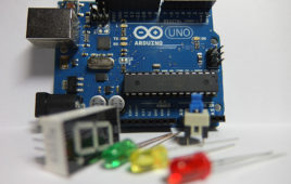
Arduino are single-board microcontrollers that are easily programmable through a USB connection. They are used with electronics to design embedded system prototypes, the Internet-of-Things (IoT), and electronic gadgets. Much like other microcontrollers, Arduino provides software-backed computing and embedded control to basic electronics applications. That means getting started with Arduino is no different than with other…
Arduino compatible coding 03: Basics of Arduino sketches and Embedded C
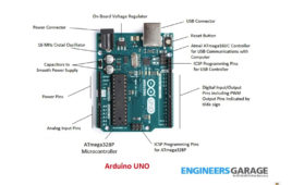
The previous tutorial included a discussion about the tools and components necessary to get started with Arduino. However, before starting with Arduino UNO (or any other Arduino board) — and experimenting with hardware projects on various sensors, actuators, and modules — it’s important to get through the basics of Arduino sketches and the embedded C…
Arduino compatible coding 04: Interfacing and driving LED by digital output
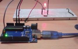
In the previous tutorial, we discussed the basics about Arduino sketches, with a a quick Arduino language reference. Now, it’s time to get our hands dirty. Interfacing LED and driving digital output from a source is the “Hello World” of embedded systems. As discussed in the previous tutorial, a microcontroller interfaces and interacts with other…
Arduino compatible coding 05: Interfacing buttons for digital input
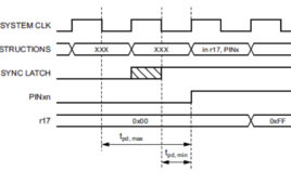
In the previous tutorial, we discussed digital output from Arduino to drive an LED. A controller can interface and interact with other devices in five ways: digital output, digital input, analog output, analog input, and serial communication. In this tutorial, we will use digital input from Arduino to read the state of a tactile switch…
Arduino compatible coding 06: Analog output (PWM) on Arduino and LED fading
In the previous tutorial, we discussed the digital input process for using Arduino. We also explained push buttons (momentary type buttons) and how to use them for data or command input via a digital input. Any controller can interface and interact with other electronic devices in five ways: digital output, digital input, analog output, analog input,…
The top MQTT brokers of 2022
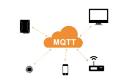
MQTT protocol is a widely used machine-to-machine communication protocol and an OASIS standard messaging protocol for the Internet of Things (IoT). With a small footprint of less than 80 Kb, MQTT is simple and based on a publish-subscribe system. The key component is the MQTT broker. IoT devices communicating over this network are called MQTT…
How to use Raspberry Pi camera module with Python

One of the main attractions of the Raspberry Pi platform is its camera module. At present, Raspberry Pi Foundation offers three camera modules: • Camera Module 2 • Camera Module 2 NoIR • Raspberry Pi High-Quality Camera The camera module 2 is a replacement for the original camera module in April 2016. The V2 module…
RPi Python Programming 10: Object-oriented Python

In the previous tutorial, we learned about the sequences and unordered collections in Python, including the operations, functions, and methods applicable to them. However, there can be more complex data structures in an application, which are known as user-defined classes and objects. Any application uses data (values/objects/user-defined classes/objects) and code behavior (how the data is…
RPi Python Programming 11: Python GUI with Tkinter
In the previous tutorial, we learned about the object-oriented features of Python, which are important for organizing code and structuring our applications. Now, let’s discuss how to design graphic interfaces in Python. Embedded applications developed on microcontrollers typically have LEDs, character LCDs, or small graphic LCDs as display devices. However, these displays do not have…
RPi Python Programming 12: Tkinter and TTK widgets

In the previous tutorial, we learned about the window widget in Tkinter and designed a blank GUI main window (which is not a child to any other window in the GUI application). Child windows serve as a container for other widgets There is no point of blank windows so there must be other widgets included…
RPi Python Programming 08: Python lists and byte arrays

In the previous tutorial, we learned about basic syntax and several elements of Python’s language. Python offers six types of sequences: strings, bytes, byte arrays, range, tuples, and lists. Importantly, the strings, bytes, range, and tuples are immutable sequences that cannot be modified once defined. It’s only possible to create or destroy these sequences. This…
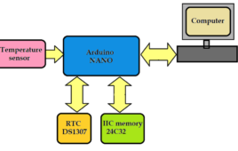
Simple data logger system with I2C memory and RTC using Arduino
Manufacturing or processing industries, like textile, chemical, pharmaceutical, and others, have many continuous processes that require monitoring and keeping a record of different physical parameters like temperature, humidity, pH, moisture, flow, viscosity, etc. So, all such parameters are continuously displayed and stored in mainframe computers. Modern industries have DCS and SCADA systems to monitor, store…
A filter design example
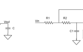
Filters are used in various fields including telecommunications where bandpass filters are used in speech recognition and modems in the audio frequency range (0 Hz to 20KHz). In the central telephone offices, high-frequency (hundreds of MHz)bandpass filters are used for channel selection. In data acquisition systems, low-pass noise filters and anti-aliasing low-pass filters are required…
Types of filter responses
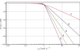
In this article, we will learn about various filter responses. A filter response helps to understand the difference between a filter’s input signal and output signal. Keeping an eye on filter responses is necessary to analyze their behaviors. To have a better understanding of the processed signal, it is important to analyze that signal and…
What are hardware filters and their types?

Filtering is a technique used to retain the wanted components and remove the unwanted components from the input signal of the system. In signal processing, this can be done by filtering out all other frequencies while retaining a specific frequency range. The signal can be filtered by using two types of filters: software and hardware.…
Designing a Switched Mode Power Supply (SMPS)
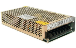
Everyone must be familiar with the term – Switched Mode Power Supply or SMPS. Yes, they are used in every personal computer. In fact, the Switched Mode Power Supply is widely used with many other devices. Once it is understood that what SMPS actually is, its countless applications can be easily imagined.
+/- 1.25V to +/-22V 1A adjustable power supply
The power supply is the mainstay for every electronic device. As the name suggests power supply are power providers for any circuit. Every electronic circuitry needs a proper power supply at the input for its optimum result at the output. We need to choose the power supply of any device or circuit as per the power requirements of the device. In this experiment, we are making an adjustable power supply, which will give voltage in the range of +/- 1.25 V to +/-22V with 1A as maximum current.
Adjustable Mini Power Supply 0V-15V
As the name suggests power supply are power providers for any circuit. Every electronic circuitry needs a proper power supply at the input for its optimum result at the output. We need to choose the power supply of any device or circuit as per the power requirements of the device. In this experiment, we are making an adjustable power supply, which will give voltage in a range of 0 – 15V with 1A as maximum current
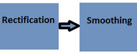
1.25V – 25V Variable power supply using bridge rectifier

The electronic devices are very sensitive to the fluctuations in the power fed to them. This problem can be solved by using regulated power supply for them. This [[wysiwyg_imageupload::]]project about power supply circuit is equipped with an adjustable voltage regulator to adjust the output in accordance with the requirement. Adjustable voltage regulators have both line and load regulation which is better than standard fixed regulators. The circuit is made using following active and passive electronic components: 1. Bridge Rectifier2. Resistors3. Capacitors 4. Variable Resistors.5. Linear Voltage Regulator IC