
The major concern in driving the LED is about the constant DC supply at the input of LED. Any unwanted fluctuation in the voltage at the input of LED can damage it. The excess flow of current through LED greater than the LED forward current rating can increase its temperature and this will damage the LED. Therefore the role of constant voltage LED supply is very important in this scenario. In this experiment, a driver circuit is designed which gives a constant voltage of 12V at the output with maximum current of 1A.
Adjustable 0-30V 2A power supply

As the name suggests power supply are power providers for any circuit. Every electronic circuitry needs a proper power supply at the input for its optimum result at the output. We need to choose the power supply of any device or circuit as per the power requirements of the device. In this experiment, we are making an adjustable power supply, which will give voltage in a range of 0 – 30V with 2A as maximum current.
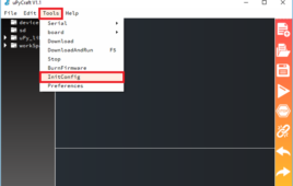
Getting started with MicroPython on ESP8266
MicroPython is an implementation of Python 3 for microcontrollers. It’s an awesome firmware that combines the powerful features of Python programming language with the low-level access of microcontrollers. Following is a list of microcontrollers supported by the MicroPython framework. Arch Mix, Actinius icarus, Arduino Nano RP2040 Connect, Arduino Primo, B_L072Z_LRWAN1, B_L475E_IOT01A, blueio_tag_evim, C3 mini, CERB40,…
How to use MicroPython with ESP8266 and ESP32 to connect to a WiFi network

ESP8266 and ESP32 are popular WiFi development boards. These single-board microcontrollers are supported by the MicroPython framework and are often used for the internet of things (IoT). Using MicroPython, ESP8266 and ESP32 can connect to the internet via WiFi and Ethernet. The MicroPython ports use Ethernet or the wireless local area network (WLAN). In this…
Using MicroPython SSD1306 driver to interface an OLED display with ESP8266 & ESP32
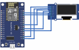
You’ve likely heard about SSD1306 or SSD1315 organic light-emitting diode (OLED) displays. These monochrome screens are typically in a similar price range as character displays, providing a more aesthetic appeal. More significantly, they provide a truly graphical interface for an embedded device. The OLED displays are available in ready-to-use breakout boards that can easily push…
How to use ESP8266’s sleep modes in MicroPython
Networking applications consume a lot of power. If such applications are battery-powered, there’s a risk the battery will exhaust because of the high power demands of networking functions. Frequently, power is also wasted in non-essential microcontroller activities. For example, the power might remain on for various built-in peripherals irrespective of their use or relevance in…
MicroPython: Time-related functions, timers & interrupts in ESP8266 and ESP32
Timers are one of the common hardware features in all microcontrollers. Timers and timer interrupts are of great use in microcontroller applications. The timer interrupts are often used when precise timing is required without a fraction of error. All MicroPython ports have one or more timers. Some of these timers may be reserved for specific…
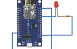
MicroPython – Reading analog signals in ESP8266 and ESP32
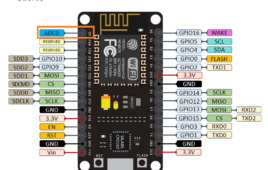
The majority of sensors have an analog output. Few sensors come with a built-in controller and can stream the output measurements over a digital protocol. That is why analog to digital conversion is one of the basic features that every microcontroller/port has. The other basic features include digital input/output, analog output, PWM generation, and serial…
RPi Python Programming 25 – Synchronous serial communication in Raspberry Pi using I2C protocol

In the previous tutorial, we discussed the basics of the I2C protocol. In most of the embedded devices, either UART otherwise I2C is used for console messages. In this tutorial, we will discuss serial communication in Raspberry Pi using the I2C protocol. I2C in Raspberry Pi For serial communication over the I2C protocol, the Broadcom…
Designing 12V Lead-Acid Battery Constant Voltage Limited Current Charger for UPS (Part- 2/17)
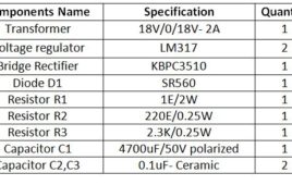
In this tutorial, a constant voltage charger for the 12V lead acid battery will be designed. The lead-acid batteries can be charged in different ways or modes. In this tutorial, a constant voltage charger will be designed for charging the lead-acid battery. The battery is required to be supplied limited current which saturates once the peak terminal voltage is achieved in the charging process. Depending on the per cell voltage of the 12V battery, the maximum rated voltage of the battery varies from 13.5 V to 14.6 V. In this tutorial, the charger circuit is designed for charging a lead acid battery having peak terminal voltage of 14.4 V.
Basics of Li-ion Battery Charging (Part- 3/17)
Lithium-ion batteries are another popular type of batteries that are used in the Uninterruptible Power Supply (UPS) designs. These batteries are commonly used in portable electronic devices. These are low maintenance batteries having high energy density, small size and light weight which makes them suitable for use in most of the portable devices. But, due to high energy density in comparison to the weight and volume of the Li-ion Battery, there are also some safety concerns while charging the Li-ion batteries. Before designing a charger circuit for these batteries, let us first understand charging methods and topologies involved in charging Li-ion batteries. Also, precautions required in handling, storing and disposing of these batteries are must to know.
Designing constant current and constant voltage source for single cell Li-ion battery charger (Part- 4/17)
In the previous tutorial, the basics of Lithium ion batteries were discussed. Also, it was discussed how it is important to handle these batteries with care. as mentioned in the previous tutorial, that Lithium ion batteries need to be charged using CC-CV method, in this tutorial, a Li-ion battery charger for a single-cell Li-ion battery of nominal voltage 3.7 V will be designed. There are charger modules available in the market which can be used to charge the Li-ion batteries. In this tutorial, a charger built using the basic electronic components including Linear Regulator will be designed from scratch. The charger circuit will be customized as per the battery specifications and the charging requirements.
Switching mechanism for linear regulator single cell Li-ion battery charger using microcontroller and relay (Part -5/17)
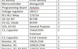
In the previous tutorial, the Constant Current (CC) Source of 60 mA and Constant Voltage (CV) Source of 4.2 V were designed using LM317 voltage regulator IC. The constant current source is to be used for constant current mode of the battery charging while the constant voltage source is to be used for constant voltage mode of the battery charging. During the designing of constant current source and the constant voltage source, testing a Li-ion battery before charging it was also discussed. Check out the previous tutorial “Basics of Li-ion battery charging” for learning about the basics of Lithium ion batteries, their charging methods and topologies.
Designing square wave inverter for UPS (Part – 6/17)
The square wave inverter is easy to design and suitable for less sensitive electronic devices. For more sensitive electronics, the supply from square wave inverter can result into noise. In this tutorial, a square wave inverter is designed which will input power from a battery and output a square AC waveform. An Inverter should generate an AC signal at the output but that signal is not necessarily an exact sine wave. A square wave can also be considered as an AC signal which can be used to drive less sensitive AC devices.
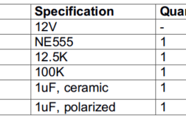
Designing Switching Mechanism with Step Up Transformer for Square Wave Inverter (Part- 7/17)

In the previous tutorial, a square wave generator was designed having a symmetric output waveform having 50 Hz frequency and 12 V peak to peak voltage. The square wave generator designed using 555 timer IC was meant to provide input square wave in the inverter circuit. Now, it is time to complete the square wave inverter circuit by adding a switching mechanism and step up transformer in the previous designed circuitry. The square wave generated from the 555 IC based circuit has peak to peak voltage of 12 V. This voltage needs to be stepped up using a step up transformer. So a step up transformer of 12V-0-12V rating is used for this purpose. But not only the voltage need to be simply stepped up, there is also a need for switching mechanism which allows drawing power from the inverter on power failure.
Gate Level Minimization – DE Part 7

In the previous tutorial, all the possible boolean functions between two variables were discussed. In the tutorial – Boolean Algebra, various theorems and postulates were stated which are useful in simplifying a boolean expression or function. However, the simplification of a boolean expression using theorems and postulates is quite cumbersome and prone to errors. Therefore, for simplification of boolean expressions, some map methods were devised. The most commonly used map method is Karnaugh Map or K-Map.
Gate Level Implementation – DE Part 8

In the previous tutorial, gate level minimization of boolean functions was discussed. A boolean function must be expressed in standard form as either sum of products (SoP) or product of sums (PoS). Once a boolean function in case is minimized to SoP or PoS form, it can be easily fabricated as two-level implementation of AND and OR gates. A two-level implementation is preferred so that there is minimum delay in signal propagation through logic gates from input to output of the digital circuit.
Introduction to VHDL & Verilog – DE Part 9

In the previous tutorials, boolean functions, boolean expressions, minimization of boolean expressions and implementation of a boolean function into logic gate diagram was discussed. It is possible to minimize a boolean function with less number of boolean variables and implement a logic gate diagram for it manually. But as the number of variables in a boolean function increases, not only its minimization becomes complex, designing a logic gate implementation for it also becomes cumbersome. In such case, computer based design tools are the ultimate resort.
Logic gate implementation of arithmetic circuits – DE Part 11
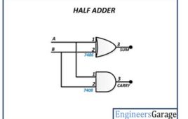
In the previous tutorial, the basic combinational arithmetic circuits like half adder, full adder, half subtractor and full subtractor were discussed in details. Now, in this tutorial, the truth table and derivation of the boolean expressions for all those circuits will be considered. With the derived boolean expressions, all those circuits will be practically designed using digital ICs.
Timers Programming in LPC1768- (Part 6/21)
This is the Article to introduce the Timer programming of ARM Cortex-M3 LPC1768 Microcontroller. Here we are going to initialize the timer peripheral in LPC1768. Timer will improve the way of usage of any microcontroller. In this tutorial we are going to set up two timers which will blink two LEDs according to the setting of the timers. Setting up the Environment for the development of ARM cortex M3 is well discussed in this article.