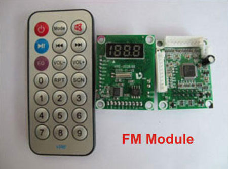
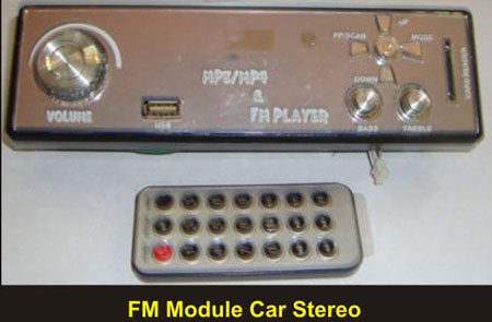
Compact sized SMD based FM Modules are now available to make FM stereo with USB provision. These FM modules are excellent circuit boards which can operate at 5 volt DC. It is also remote operated and the output can be connected to a power amplifier or VCD player. It has a Digital display to show the different functions like Mode, Channel, Volume etc. It also has SD card reader. It is low cost and reliable and can be wired easily. But it is necessary to know the PCB points to wire the board . This note will help you to make your FM receiver.
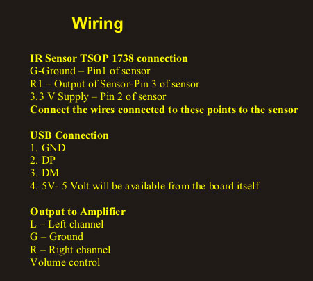
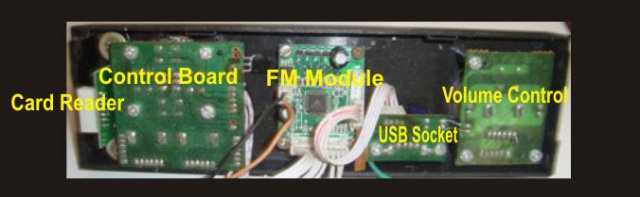
The circuit board is available as Pre assembled board with connecting wires. It is necessary to connect Remote Sensor (TSOP 1738), USB socket and Amplifier with Speaker.
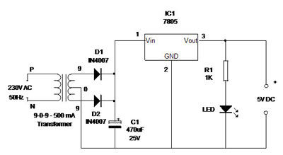
The circuit requires 5 Volt regulated power supply. If the power supply is not well regulated or with ripples, performance of the circuit will be poor. Regulated power supply can be obtained from a 9 volt transformer and 7805 Voltage regulation IC. The power supply circuit is shown below. The Amplifier can be powered from the 9V unregulated DC available from the point connecting Pin 1 of the Regulator IC.
Connections
On the PCB, there are markings for wire connections and wire sets are provided along with the kit. The markings on the back of the PCB are :
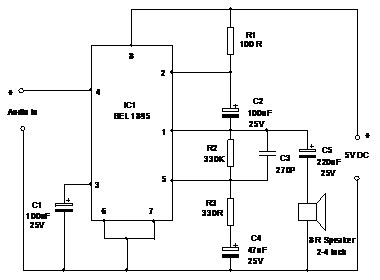
BEL 1895 Low Power Mono Amplifier
BEL 1895 Low Power Mono Amplifier
To make a compact unit use the IC BEL 1895 which can give 1 W output to drive a small speaker. The circuit given is a Mono Amplifier. If you need stereo, assemble two similar amplifier circuits. Alternately you can use a Pre assembled amplifier board. IC BEL 1895 works between 3- 5 volts.
LA 4440 High Power Stereo Amplifier
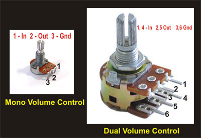
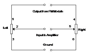
If high output is necessary, the Module can be connected to a Power Amplifier. The 20 Watts LA4440 Stereo power amplifier circuit is given below. The FM module has outputs for Left and Right channels so that the input to Amplifier can be given through a 10 K Lin (Linear) Dual volume control.
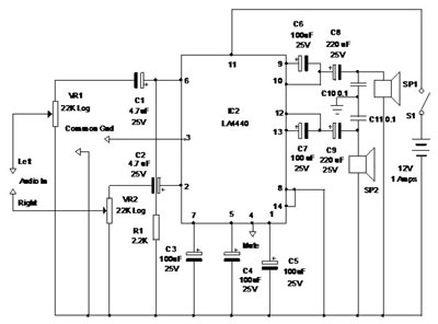
Use a 10 K Lin Dual volume control between the output lines (L and R) of the module and the amplifier. Set minimum volume (2 to 4) in the module using remote and adjust 10 K pot to get clear sound from the speaker. Then increase the volume using remote to the required level. The module can give 1 to 50 range volume.
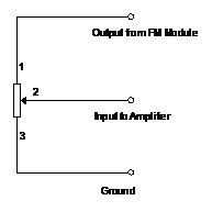
Volume Control Connection
Antenna
Antenna is necessary if the signal strength is weak .Connect 30 cm plastic wire to the point ANT on the PCB.
Remote less operation
On the PCB, connections V+, PM, CH V-, P etc are given to connect membrane switches for manual operation.
Tuning
The FM board has delicate components. Connect wires carefully. To get FM stations programmed, first use a long plastic wire ( 3 meters) as antenna. There is a point in the board ANT to connect antenna. If you scan FM stations using the Scan button of Remote, it will automatically search all the available stations and save the stations as P1, P2, P3 etc. After that, a short piece of wire (30 cm) is sufficient for antenna. You can also use a Telescopic antenna.
Note: If there is a hum from the speaker, not connect the Gnd wire of output in FM module .Connect only two lines – Output from Module to the first pin of Volume control and Input to the amplifier from the second pin of volume control. Third pin of volume control is ground connection.
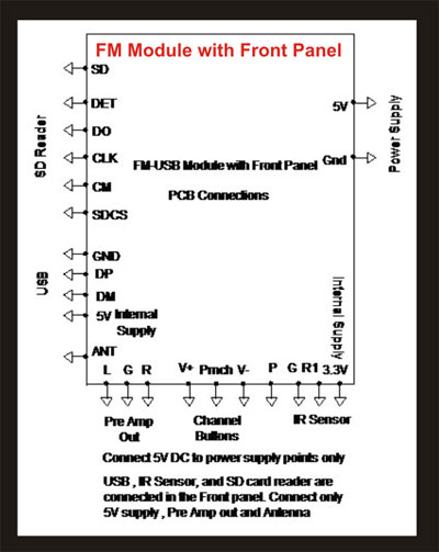
FM Module with Front Panel
FM Module having front panel with fixed USB socket and SD card reader, mp4, video boards etc is also available.
Filed Under: Electronic Projects

Questions related to this article?
👉Ask and discuss on EDAboard.com and Electro-Tech-Online.com forums.
Tell Us What You Think!!
You must be logged in to post a comment.