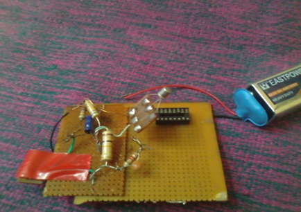
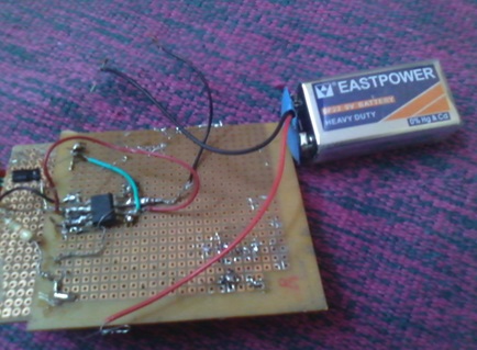
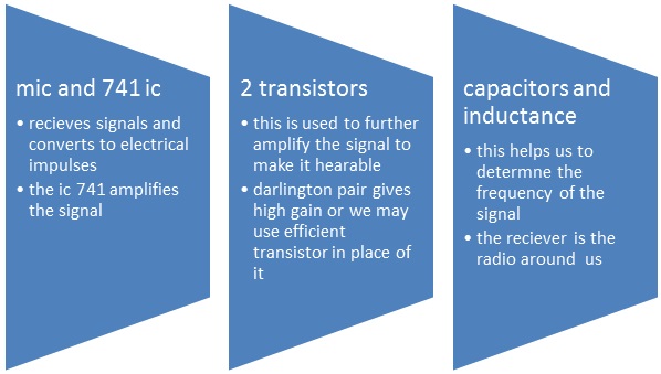
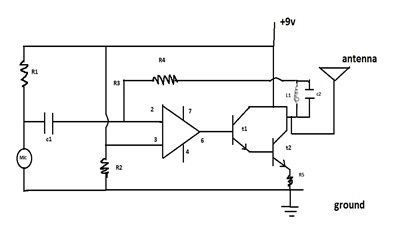
The proposed simple electronic spy bug circuit is basically a high gain amplifier using the IC 741 as the heart of the circuit and also a couple of high gain output transistors. The IC 741 if configured as a non-inverting amplifier which performs the function of a pre-amplifier stage. The gain of this IC 741 preamplifier stage may be varied as desired, using the pot across its input and output pin outs. The gain setting is used to set the sensitivity of the amplifier and is set to maximum so that even low volume speech conversation may be picked through it. The mic at the input transforms sound vibrations into minute electrical pulses, which is further amplified by the IC 741 to suitable levels before applying it to the output amplifier stage consisting of a standard DARLINGTON stage. This Darlington stage is made using a couple of high gain transistors bc107A’s.Here, the signal received from the 741 output is suitably amplified so that it finally sent whether to the headphone or to the antenna here i have shown to the antenna we can use the output for the headphone also. we may worry about the external nine volt given to the circuit as so to make the signal powerful from the input side and also at the output side. If this won’t work then use 20k pot in the R1 .here in the circuit i have used one transistor which is also efficient to work.


Conclusion:
Result can be found in the radio as we set the frequency or we search the signal. Here signal can be stronger if we use the shorter antenna. This could be more sensitive if u don’t solder the mic and it worked you will be able to hear it in low pitch.
Calculations:

Set the required value for the transmission frequency
So for example:
For F=100.5 Mhz and let’s take the L1=22nH
Then we have the capacitance value as 1000uF
So work it out all the best!!!
CIRCUIT DIAGRAM:
Parts List for the above op-amp based spy bug
R1 = 10K,
R3, R4 = 27K,
R4= 1.5 M,
R5= 50K,
C1 = 104,
C2 = 220uF/25V,
T1 = BC107A,
T2 = BC107A,
L1=22nH
MIC = electret mic,
IC1 = 741,
Power = 9 volt battery
Circuit Diagrams
Filed Under: Electronic Projects


Questions related to this article?
👉Ask and discuss on Electro-Tech-Online.com and EDAboard.com forums.
Tell Us What You Think!!
You must be logged in to post a comment.