Engineers Garage

  • Projects and Tutorials
    • Electronic Projects
      • 8051
      • Arduino
      • ARM
      • AVR
      • PIC
      • Raspberry pi
      • STM32
    • Tutorials
    • Circuit Design
    • Project Videos
    • Components
  • Articles
    • Tech Articles
    • Insight
    • Invention Stories
    • How to
    • What Is
  • News
    • Electronic Products News
    • DIY Reviews
    • Guest Post
  • Forums
    • EDABoard.com
    • Electro-Tech-Online
    • EG Forum Archive
  • Digi-Key Store
    • Cables, Wires
    • Connectors, Interconnect
    • Discrete
    • Electromechanical
    • Embedded Computers
    • Enclosures, Hardware, Office
    • Integrated Circuits (ICs)
    • Isolators
    • LED/Optoelectronics
    • Passive
    • Power, Circuit Protection
    • Programmers
    • RF, Wireless
    • Semiconductors
    • Sensors, Transducers
    • Test Products
    • Tools
  • EE Resources
    • DesignFast
    • LEAP Awards
    • Oscilloscope Product Finder
    • White Papers
    • Webinars
  • EE Learning Center
  • Women in Engineering

FM Transmitter Bug: Learn how to Make one

By Ashutosh Bhatt

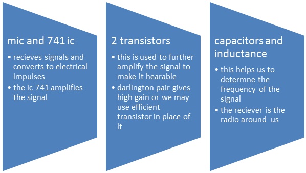
The proposed simple electronic spy Bug circuit is basically a high gain amplifier using the IC 741 as the heart of the circuit and also a couple of high gain output transistors. The IC 741 if configured as a non-inverting amplifier which performs the function of a pre-amplifier stage. The gain of this IC 741 preamplifier stage may be varied as desired, using the pot across its input and output pin outs.

The gain setting is used to set the sensitivity of the amplifier and is set to maximum so that even low volume speech conversation may be picked through it. The mic at the input transforms sound vibrations into minute electrical pulses, which is further amplified by the IC 741 to suitable levels before applying it to the output amplifier stage consisting of a standard DARLINGTON stage. This Darlington stage is made using a couple of high gain transistors bc107A's.


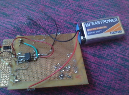
.Here, the signal received from the 741 output is suitably amplified so that it finally sent whether to the headphone or to the  antenna here i have shown to the antenna we can use the output for the headphone also. we may worry about the external nine volt given to the circuit as so to make the signal powerful from the input side and also at the output side. If  this  won’t work then use 20k pot in the R1  .here in the circuit i have used one transistor which is also efficient to work.

Prototype of FM Transmitter Circuit

Circuit for FM Transmitter Bug

FM Transmitter Bug Circuit Components

Conclusion:

Result can be found in the radio as we set the frequency or we search the signal. Here signal can be stronger if we use the shorter antenna. This could be more sensitive if u don’t solder the mic and it worked you will be able to hear it in low pitch.

Calculations:

Formula to calculate Capitcance Value

Set the required value for the transmission frequency

So for example:

For F=100.5 Mhz and let’s take the L1=22nH

Then we have the capacitance value as 1000uF

So work it out all the best!!!

CIRCUIT DIAGRAM:

Parts List for the above op-amp based spy bug

R1 = 10K,

R3, R4 = 27K,

R4= 1.5 M,

R5= 50K,

C1 = 104,

C2 = 220uF/25V,

T1 = BC107A,

T2 = BC107A,

L1=22nH

MIC = electret mic,

IC1 = 741,

Power = 9 volt battery


Circuit Diagrams

Circuit-Diagram-FM-Transmitter-Bug


Filed Under: Circuit Design
Tagged With: spy bug, transmitter bug
 

Questions related to this article?
👉Ask and discuss on Electro-Tech-Online.com and EDAboard.com forums.


Tell Us What You Think!! Cancel reply

You must be logged in to post a comment.

HAVE A QUESTION?

Have a technical question about an article or other engineering questions? Check out our engineering forums EDABoard.com and Electro-Tech-Online.com where you can get those questions asked and answered by your peers!


Featured Tutorials

  • Designing Gate Driver Circuit and Switching Mechanism for Modified Sine Wave Inverter – (Part 9/17)
  • Completing Modified Sine Wave Inverter Design with Full Bridge Circuit and Step Up Transformer – (Part 10/17)
  • Designing an Offline UPS – Part (12 /17)
  • How to reduce Switching Time of a Relay – (Part 15/17)
  • Testing MOSFET – (Part 16/17)
  • Driving High Side MOSFET using Bootstrap Circuitry – (Part 17/17)

Stay Up To Date

Newsletter Signup

Sign up and receive our weekly newsletter for latest Tech articles, Electronics Projects, Tutorial series and other insightful tech content.

EE Training Center Classrooms

EE Classrooms

Recent Articles

  • Designing Gate Driver Circuit and Switching Mechanism for Modified Sine Wave Inverter – (Part 9/17)
  • Completing Modified Sine Wave Inverter Design with Full Bridge Circuit and Step Up Transformer – (Part 10/17)
  • Designing an Offline UPS – Part (12 /17)
  • How to reduce Switching Time of a Relay – (Part 15/17)
  • Testing MOSFET – (Part 16/17)

Most Popular

5G 555 timer circuit 8051 ai Arduino atmega16 automotive avr dc motor display Electronic Part Electronic Parts Fujitsu ic infineontechnologies integratedcircuit Intel IoT ir lcd ldr led maximintegratedproducts microchip microchiptechnology Microchip Technology microcontroller microcontrollers mosfet motor powermanagement Raspberry Pi remote renesaselectronics Research robot samsung semiconductor sensor software STMicroelectronics switch Technology vishayintertechnology wireless

RSS EDABOARD.com Discussions

  • Please help to identify the signal input port on board
  • Hotplugging UART
  • RF switch selection
  • sensitivity in filters and number of bits of system
  • MDO4104-6 Front Panel Not Working

RSS Electro-Tech-Online.com Discussions

  • software PWM
  • Combination of Wires of two DC motor giving Output current.
  • Passthrough charging-simple but impossible to achieve?
  • geared motor to revolve oval platform
  • None existant errors (MPLAB X)
Engineers Garage
  • Analog IC TIps
  • Connector Tips
  • DesignFast
  • EDABoard Forums
  • EE World Online
  • Electro-Tech-Online Forums
  • Microcontroller Tips
  • Power Electronic Tips
  • Sensor Tips
  • Test and Measurement Tips
  • 5G Technology World
  • About Us
  • Contact Us
  • Advertise

Copyright © 2022 WTWH Media LLC. All Rights Reserved. The material on this site may not be reproduced, distributed, transmitted, cached or otherwise used, except with the prior written permission of WTWH Media
Privacy Policy | Advertising | About Us

Search Engineers Garage

  • Projects and Tutorials
    • Electronic Projects
      • 8051
      • Arduino
      • ARM
      • AVR
      • PIC
      • Raspberry pi
      • STM32
    • Tutorials
    • Circuit Design
    • Project Videos
    • Components
  • Articles
    • Tech Articles
    • Insight
    • Invention Stories
    • How to
    • What Is
  • News
    • Electronic Products News
    • DIY Reviews
    • Guest Post
  • Forums
    • EDABoard.com
    • Electro-Tech-Online
    • EG Forum Archive
  • Digi-Key Store
    • Cables, Wires
    • Connectors, Interconnect
    • Discrete
    • Electromechanical
    • Embedded Computers
    • Enclosures, Hardware, Office
    • Integrated Circuits (ICs)
    • Isolators
    • LED/Optoelectronics
    • Passive
    • Power, Circuit Protection
    • Programmers
    • RF, Wireless
    • Semiconductors
    • Sensors, Transducers
    • Test Products
    • Tools
  • EE Resources
    • DesignFast
    • LEAP Awards
    • Oscilloscope Product Finder
    • White Papers
    • Webinars
  • EE Learning Center
  • Women in Engineering