Engineers Garage

  • Electronics Projects and Tutorials
    • Electronic Projects
      • Arduino Projects
      • AVR
      • Raspberry pi
      • ESP8266
      • BeagleBone
      • 8051 Microcontroller
      • ARM
      • PIC Microcontroller
      • STM32
    • Tutorials
      • Audio Electronics
      • Battery Management
      • Brainwave
      • Electric Vehicles
      • EMI/EMC/RFI
      • Hardware Filters
      • IoT tutorials
      • Power Tutorials
      • Python
      • Sensors
      • USB
      • VHDL
    • Circuit Design
    • Project Videos
    • Components
  • Articles
    • Tech Articles
    • Insight
    • Invention Stories
    • How to
    • What Is
  • News
    • Electronic Product News
    • Business News
    • Company/Start-up News
    • DIY Reviews
    • Guest Post
  • Forums
    • EDABoard.com
    • Electro-Tech-Online
    • EG Forum Archive
  • DigiKey Store
    • Cables, Wires
    • Connectors, Interconnect
    • Discrete
    • Electromechanical
    • Embedded Computers
    • Enclosures, Hardware, Office
    • Integrated Circuits (ICs)
    • Isolators
    • LED/Optoelectronics
    • Passive
    • Power, Circuit Protection
    • Programmers
    • RF, Wireless
    • Semiconductors
    • Sensors, Transducers
    • Test Products
    • Tools
  • Learn
    • eBooks/Tech Tips
    • Design Guides
    • Learning Center
    • Tech Toolboxes
    • Webinars & Digital Events
  • Resources
    • Digital Issues
    • EE Training Days
    • LEAP Awards
    • Podcasts
    • Webinars / Digital Events
    • White Papers
    • Engineering Diversity & Inclusion
    • DesignFast
  • Guest Post Guidelines
  • Advertise
  • Subscribe

FM Transmitter

By Wani Sageer April 26, 2012

The above circuit is a simple VHF FM transmitter circuit. It is basically a VHF colipits oscillator capable of transmitting sound or music to any standard FM receiver.FM Transmitter
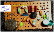
The circuit works on a small 9V battery which makes it easily portable. It also has a capacitor microphone which picks up very weak sound signals. The output frequency can be easily changed by varying the potential meter and the frequency stability is quiet good. The range of this transmitter is 60 to 100meters.
 
Features:
•Electrically Adjustable frequency between 88 and 108MHZ.
• Portable and low power consumption.
• Use with any FM receiver.
• Powered by 9 Volt battery.
 
How It Works:
The transmitter uses the frequency modulation technique. So it evident that in Frequency Modulation, the amplitude of RF carrier stays constant while as frequency varies according to the intensity of the audio signal. As the input amplitude of signal increases (i.e. during the positive half cycles) the frequency of the carrier increases too, on the other hand when the input signal decreases in amplitude (negative half-cycle or no signal) the carrier frequency decreases accordingly. When we speak something through our mouth the sound waves, which are pressure waves, hits the diaphragm of the capacitor microphone which are converted into electrical signal. This electrical signal is fed to the transistor’s base which changes the output frequency of the transmitter. The output frequency of the transmitter is adjustable from 88 to 108 MHz under commercial FM band.

Circuit Description

The heart of the FM Transmitter circuit is a (VHF/UHF) oscillator transistor C1730 operates under class A .Resistors R2, R3 and   R4 provides the necessary bias to the transistor for proper operation. Resistor R1 provides bias to the FET based capacitor microphone. Capacitor C1 is a coupling capacitor which couples the audio signal to the base of the transistor through L1.
 
L1 is an Rfc choke which chokes all high frequencies entering to the microphone. Capacitor C2 is a decoupling capacitor to high frequencies appearing at microphone. Capacitor C3 is RF ground to the transistor. The values of the tank elements (L2, C4, and C5 & C6) depend upon the chosen fundamental frequency.
2pif=1/root LCT
L=L2
CT=C4C5 /(C4+C5) II C6
Since C6 is chosen to limit the upper frequency which is a parallel component to C4 & C5. Therefore for higher frequency use it is recommended to decrease the value of L2. In the above circuit changing the value of C6 will also change the output frequency. Inductor L2 is an RF oscillator coil which is chosen to tune somewhere between 88 & 108MHZ band. Capacitor C8 and C9 is RF decoupling capacitor which prevents all Radio frequencies entering to power lines. Rfc L3 chokes out Radio frequencies. Capacitor C7 is a tuning capacitor. C10 is a coupling capacitor between Transmitter & antenna. VR-1 controls the voltage of varicap diode through RF isolating resistor R5. Resistor R6 and Zener diode Z1 is a 5V shunt voltage regulator, which regulates 5.1V to varicap diode, so as to minimize the frequency drift which may cause due to low or high input voltage. Capacitor C11 is used across Z1 to ensure a better RF isolation.  Any type of 20 to 25cm telescopic antenna can be used. The range of this transmitter is 60 to 100mts.
Note..This is a VHF/RF project so more care is needed during soldering and Placement of all components. So keep all the leads/components as shortest as possible to minimize stray capacitance and inductance. The transmitter can be modified to any frequency between 50 & 400 MHz by replacing L2 & C6. It is strongly recommended to use a proper aluminum shielding above 150 MHZ to minimize the stray capacitances and inductance.


Parts List

Parts list:
R1= 10K
R2= 15K
R3= 3.3K
R4= 470 ohms
R5= 100K
R6= 4.7K
VR 1= 10K Pot meter
 
VALUE               CAPACITOR CODE
C1= 0.1uF———————104
C2= 0.001uf——————-102
C3= 0.0015uF—————-152
C4= 10pf———————–10
C5= 3pf ————————3
C6= 2.5pf———————-2.5
C7= 10pf———————–10
C8= 0.01uF——————-103
C9= 0.022uF—————–223
C10= 1pf———————-1
C11= 0.001uf—————–102
 
Inductor
L1 & L3= 4.7uH Rfc      color code= yellow, violet & silver as tolerance
L2= 5.5 turns close wound, SWG 23, internal dia of coil=5mm.
M1= CONDENSER MICROPHONE
T1= S9018 or 2SC1730 or 2SC1906 or any similar type having fT of 1.1 GHz
Z1= 5.1V, 500mW Zener diode
VC1= varicap diode BB109 or similar


Project Source Code


Circuit Diagrams

FM-Transmitter-Circuit


Filed Under: Electronic Projects
Tagged With: fm, transmitter
 

Next Article

← Previous Article
Next Article →

Questions related to this article?
👉Ask and discuss on EDAboard.com and Electro-Tech-Online.com forums.


Tell Us What You Think!! Cancel reply

You must be logged in to post a comment.

EE TECH TOOLBOX

“ee
Tech Toolbox: Internet of Things
Explore practical strategies for minimizing attack surfaces, managing memory efficiently, and securing firmware. Download now to ensure your IoT implementations remain secure, efficient, and future-ready.

EE Learning Center

EE Learning Center
“engineers
EXPAND YOUR KNOWLEDGE AND STAY CONNECTED
Get the latest info on technologies, tools and strategies for EE professionals.

HAVE A QUESTION?

Have a technical question about an article or other engineering questions? Check out our engineering forums EDABoard.com and Electro-Tech-Online.com where you can get those questions asked and answered by your peers!


RSS EDABOARD.com Discussions

  • RFsoc4x2 fpga diagram request
  • BOM sent to Contract assemblers doesnt correspond to schem
  • Half-bridge LLC resonant converter using UCC25600
  • Lightbox circuit help
  • Transistor circuit in audio

RSS Electro-Tech-Online.com Discussions

  • Kawai KDP 80 Electronic Piano Dead
  • An Update On Tarrifs
  • Trying to use a L9110s motor driver chip
  • I want to make a CRT with some modifications But i have no Idea where to start
  • Funny Images Thread!

Featured – Designing of Audio Amplifiers part 9 series

  • Basics of Audio Amplifier – 1/9
  • Designing 250 Milli Watt Audio Power Amplifier – 2/9
  • Designing 1 Watt Audio Power Amplifier – 3/9
  • Designing a Bass Boost Amplifier – 4/9
  • Designing a 6 Watt Car Audio Amplifier – 5/9
  • Design a low power amplifier for headphones- 6/9

Recent Articles

  • Fischer connector system adds ratchet locking system designed for 300g shock resistance
  • Littelfuse introduces tactile switch with enhanced bracket peg design for mounting strength
  • Infineon releases GaN switch with monolithic bidirectional design
  • Sienna Semiconductor data converters feature sample rates from 20 to 250 Msps
  • Delta’s 5,500 W power supplies achieve 97.5% energy efficiency for AI servers

EE ENGINEERING TRAINING DAYS

engineering

Submit a Guest Post

submit a guest post
Engineers Garage
  • Analog IC TIps
  • Connector Tips
  • Battery Power Tips
  • DesignFast
  • EDABoard Forums
  • EE World Online
  • Electro-Tech-Online Forums
  • EV Engineering
  • Microcontroller Tips
  • Power Electronic Tips
  • Sensor Tips
  • Test and Measurement Tips
  • 5G Technology World
  • Subscribe to our newsletter
  • About Us
  • Contact Us
  • Advertise

Copyright © 2025 WTWH Media LLC. All Rights Reserved. The material on this site may not be reproduced, distributed, transmitted, cached or otherwise used, except with the prior written permission of WTWH Media
Privacy Policy

Search Engineers Garage

  • Electronics Projects and Tutorials
    • Electronic Projects
      • Arduino Projects
      • AVR
      • Raspberry pi
      • ESP8266
      • BeagleBone
      • 8051 Microcontroller
      • ARM
      • PIC Microcontroller
      • STM32
    • Tutorials
      • Audio Electronics
      • Battery Management
      • Brainwave
      • Electric Vehicles
      • EMI/EMC/RFI
      • Hardware Filters
      • IoT tutorials
      • Power Tutorials
      • Python
      • Sensors
      • USB
      • VHDL
    • Circuit Design
    • Project Videos
    • Components
  • Articles
    • Tech Articles
    • Insight
    • Invention Stories
    • How to
    • What Is
  • News
    • Electronic Product News
    • Business News
    • Company/Start-up News
    • DIY Reviews
    • Guest Post
  • Forums
    • EDABoard.com
    • Electro-Tech-Online
    • EG Forum Archive
  • DigiKey Store
    • Cables, Wires
    • Connectors, Interconnect
    • Discrete
    • Electromechanical
    • Embedded Computers
    • Enclosures, Hardware, Office
    • Integrated Circuits (ICs)
    • Isolators
    • LED/Optoelectronics
    • Passive
    • Power, Circuit Protection
    • Programmers
    • RF, Wireless
    • Semiconductors
    • Sensors, Transducers
    • Test Products
    • Tools
  • Learn
    • eBooks/Tech Tips
    • Design Guides
    • Learning Center
    • Tech Toolboxes
    • Webinars & Digital Events
  • Resources
    • Digital Issues
    • EE Training Days
    • LEAP Awards
    • Podcasts
    • Webinars / Digital Events
    • White Papers
    • Engineering Diversity & Inclusion
    • DesignFast
  • Guest Post Guidelines
  • Advertise
  • Subscribe