In 21st century the field of robotics have emerged very quickly and continues to bringing new technological advances to many sectors of society.With the belief that it’s only a matter of time before the robots rise and replace all humans. The robots are not only being used in automotive and medical industries for doing work but now it is also used for entertainment purpose such as games.
This project is inspired from Kuka Robot one of the fastest robot on earth specialized in table tennis manufactured in Germany and flappy bird one of the game which was automated and played by image processing phenomena. In this project, the game “Racing Moto” one of the popular mobile app is automated by robotic hand.

Fig. 1: Prototype of Arduino based Mobile Game Console
WORKING:
Racing moto is a game in which there are 3 lanes and cars or obstacles can come in any of the lane. To avoid the bike from hitting the obstacle it is necessary to tilt it at any particular angle. Robotic hand plays this game by help of servo motor which is programmed to rotate and change its position whenever it senses the presence of an obstacle. For this project reader should have knowledge of how to start with arduino .
The sensors used for this purpose are phototransistors. Phototransistor switches on and off whenever light intensity changes. Light intensity is different when there is no obstacle under the sensor and different when obstacle is present. This change in intensities can be observed on the analog channels of arduino uno. These values or change in intensities are used to keep the hand in motion means when rotation is required it will rotate at particular angle. Three LED’s are also used which somehow plays an important part in this project. These LED’s will glow when the obstacle will be under the phototransistors and will help to find out whether the values that are selected to detect the presence of obstacle are correct or not.

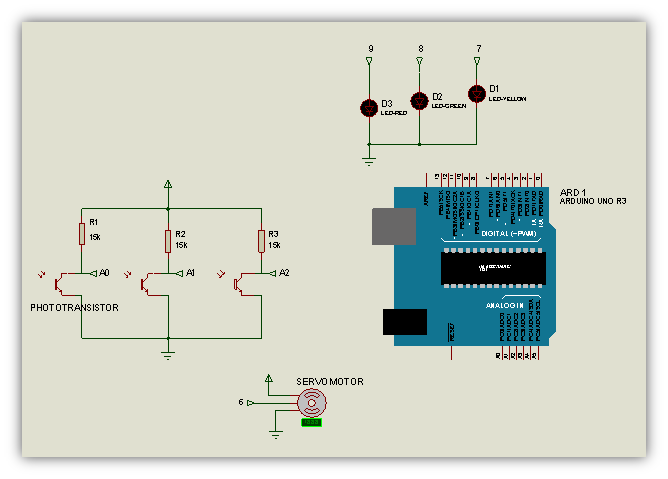
Fig. 2: Circuit Diagram and image of Photo Transistor Circuit used in Game Console
Steps
STEP1:
Next step is to make the circuit on Vero board i.e. one end of 15k? resistor is placed with the collector of phototransistor while the other end of resistor is supplied with 5 volts power supply and the emitter of the transistor is grounded. The analog pin of arduino is placed at the junction between collector and resistor. Three circuits in same configuration is made.
In the circuit given below Q1, Q2 and Q3 are the phototransistors and A0,A1 and A2 are the analog input pins of arduinouno from which the values will be observed.

Fig. 3: Circuit Diagram and Image of LED Circuit used in Game Console
STEP2:
Once the values are selected, to check and satisfy that the values are either correct or not means whether the values are differentiating between the presence and absence of obstacle or not. For this reason three LED’s are placed in the circuit. They will glow each time the intensity crosses the threshold range.
The three LEDs one for each lane are connected to the digital output pins of arduino (i.e. digital pins 7, 8 and 9). They will glow ‘ON’ when sensor will detect the presence of cars and will remain ‘OFF’ when no car present.
Here in this figure, LED (D3) attached with digital pin 9 is ‘ON’ which indicates that the car is detected at analog pin A2 (further explained in next step).
STEP3:

Fig. 4: Image of cardboard made mobile holder for Game Console
The analog pins (A0,A1,A2) and digital pins(7,8,9) are related with each other in such a manner that the instance at which the car will be right under the sensor, the analog pin (A0) will cross its set threshold range which means the LED at pin 7 will GLOW at that time else remains OFF. Similarly A1 and A2 are linked with pins 8 and 9 respectively.
STEP4:

Fig. 5: Image of Arduino based Game Console Circuit
In Racing Moto, the direction of the bike is controlled by tilting the cell phone. This can be done by robotic hand which consists of servo motor. This motor is programmed to tilt the hand at desired angle. The mobile phone is placed in the base (any material can be used as base). Here a box is used which is made same as that the size of the mobile with small roof so that the Vero board (sensor circuit) can be mounted on the mobile. This box is placed on the gripper of the robotic hand.
Components Used
COMPONENTS
Arduino Uno :
Arduino is a single-board microcontroller, intended to make the application of interactive objects or environments more accessible. The Arduino Uno is a microcontroller board based on the ATmega328. It has 14 digital input/output pins (of which 6 can be used as PWM outputs), 6 analog inputs, a 16 MHz ceramic resonator, a USB connection, a power jack, an ICSP header, and a reset button. It contains everything needed to support the microcontroller.

Fig. 6: Typical Image of Arduino Uno
Resistor:
A resistor is a passive two-terminal electrical component that implements electrical resistance as a circuit element. Resistors act to reduce current flow, and, at the same time, act to lower voltage levels within circuits. Resistors may have fixed resistances or variable resistances, such as those found in thermistors, trimmers, photoresistors, piezoresistors and potentiometers.
Resistors are common elements of electrical networks and electronic circuits and are ubiquitous in electronic equipment.

Fig. 7: Typical Image of Resistors
Phototransistor:
A semiconductor device that is highly sensitive to light. Photonic transistors are used in switching and amplifying applications, and they can conduct current in either direction .
They are the transistors that regulates current or switches it on and off based on the intensity of the light it is exposed to rather than an external electric signal.

Fig. 8: Typical Image of Phototransistors
Robotic Hand:
A robotic hand is a type of mechanical hand, usually programmable, with similar functions to a human hand. The arm may be the sum total of the mechanism or may be part of a more complex robot. The links of such a manipulator are connected by joints allowing rotational motion (such as in an articulated robot)

Fig. 9: Typical Image of Robotic Hand
The robotic hand delivers fast, accurate, and repeatable movement. The robot features:
· Wrist motion
· Functional gripper
· Wrist rotate
PCB Design

Fig. 10: PCB Layout of Arduino Circuit controlling Robotic Hand
Project Source Code
###


#include <Servo.h>
Servo myservo;                 // create servo object to control a servo
int led1=8,led2=9,led3=10 ;
void setup()
{
Serial.begin(9600);         // initialize serial communication at 9600 bits per second
pinMode(led1,OUTPUT);
pinMode(led2,OUTPUT);
pinMode(led3,OUTPUT);
myservo.attach(6);          // attaches the servo on pin 6 to the servo object
   }
void loop()
{
int sensorValue1 = analogRead(A0);    // read the input on analog pin 0:
int sensorValue2 = analogRead(A1);    // read the input on analog pin 1:
int sensorValue3 = analogRead(A2);    // read the input on analog pin 2:
  // print out the value
Serial.println(sensorValue1);
Serial.println(sensorValue2);
Serial.println(sensorValue3);
Serial.println(" ");
if(sensorValue1>1013||sensorValue1<=981)          // threshold values for cars
digitalWrite(led1,HIGH);                                     // led will glow when intensity crosses the                                                                                       threshold range.
if(sensorValue1<=1013 &&sensorValue1>981)      // threshold values for road
digitalWrite(led1,LOW);                                    // led will remain off in between this range.
if(sensorValue2>=988||sensorValue2<929)          // threshold values for cars
digitalWrite(led2,HIGH);
if(sensorValue2<988&&sensorValue2>=929)           // threshold values for road
digitalWrite(led2,LOW);
if(sensorValue3>=983||sensorValue3<=904)          // threshold values for cars
digitalWrite(led3,HIGH);
if(sensorValue3<983&&sensorValue3>904)             // threshold values for road
digitalWrite(led3,LOW);
delay(5);                                                           // delay in between reads for stability
// motor will be at 90 when there is no car.
if((sensorValue1<=1013 &&sensorValue1>=981)&&(sensorValue2<988&&sensorValue2>=929)&& (sensorValue3<983&&sensorValue3>904))
{
myservo.write(90);
  }
// motor will be at 90 when car is in 1st lane
if((sensorValue1>1013||sensorValue1<=981)&&(sensorValue2<988&&sensorValue2>=929)&&(sensorValue3<983&&sensorValue3>904))
{
myservo.write(90);
delay(200);
}
// motor will be at 83 when car is in 2nd lane.
if((sensorValue1<=1013 &&sensorValue1>981)&&(sensorValue2>=988||sensorValue2<929)&&(sensorValue3<983&&sensorValue3>904))
{
myservo.write(83);
delay(200);
}
// motor will be at 90 when car is in 3rd lane.
if((sensorValue1<=1013 &&sensorValue1>981)&&(sensorValue2<988&&sensorValue2>=929)&&(sensorValue3>=983||sensorValue3<=904))
{
myservo.write(90);
delay(200);
}
// motor will be at 97 when cars are in 1st and 2nd lane.
if((sensorValue1>1013||sensorValue1<981)&&(sensorValue2>=988||sensorValue2<929)&&(sensorValue3<983&&sensorValue3>904))
{
myservo.write(97);
delay(200);
}
// motor will be at 83 when cars are in 2nd and 3rd lane.
if((sensorValue1<=1013 &&sensorValue1>981)&&(sensorValue2>=988||sensorValue2<929)&&(sensorValue3>=983||sensorValue3<=904))
{
myservo.write(83);
delay(200);
}
// motor will be at 90 when cars are in 1st and 3rd lane.
if((sensorValue1>1013 ||sensorValue1<=981)&&(sensorValue2<988&&sensorValue2>=929)&&(sensorValue3>=983||sensorValue3<=904))
{
myservo.write(90);
delay(200);
}
}

###
Circuit Diagrams
Project Video
Filed Under: Electronic Projects
Filed Under: Electronic Projects

Questions related to this article?
👉Ask and discuss on EDAboard.com and Electro-Tech-Online.com forums.
Tell Us What You Think!!
You must be logged in to post a comment.